Start and stop of a single phase Motor wiring
Learn single-phase motor wiring with a contactor diagram, including DP switch/MCB protection, starter coil, safe operation, and a step-by-step installation guide.

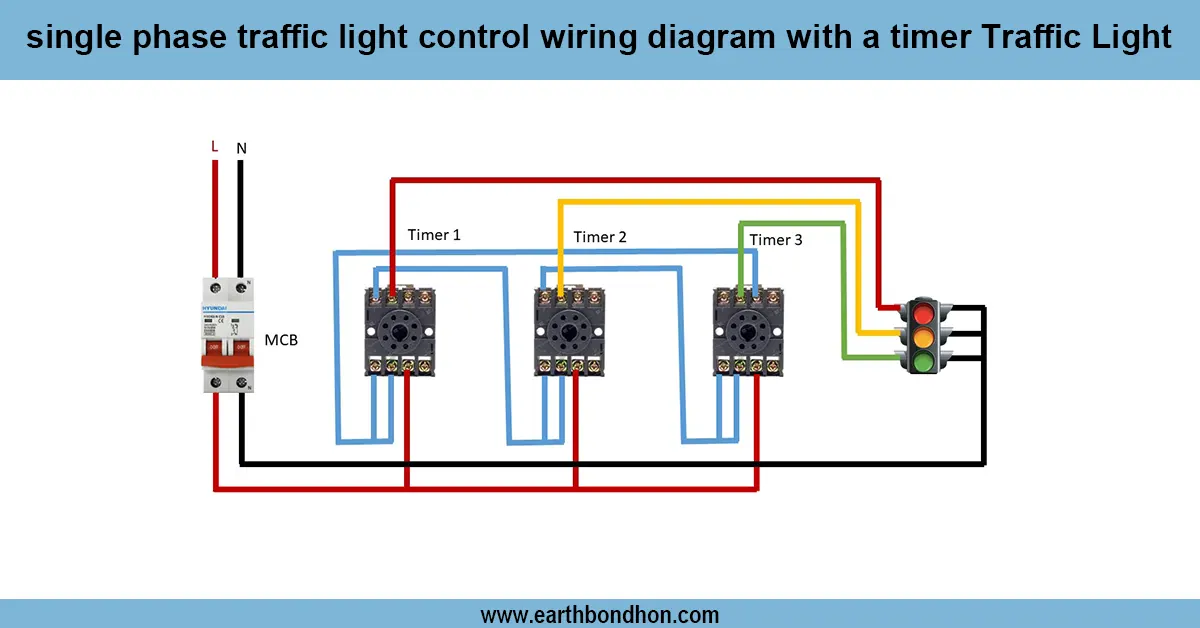
single phase motor control wiring diagram
A one-phase motor with contactor diagram illustrates the supply to the contactor coil and coiled motor terminals as fed by the DP switch or MCB feed, and makes the contactor alternative or automatic control safe.
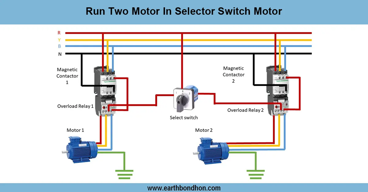
single phase motor contactor connection:
A single-phase motor with a contactor enables a motor to be controlled remotely or automatically, safely and conveniently. Protection of the incoming phase and neutral is provided by a DP switch or an MCB. The main motor feed connection is under the contactor coil, which can be triggered manually either by push buttons or automatically by timers or relays. The contactor output is connected to the motor terminal, and therefore, the motor will only operate when the contactor is not in the low state. Earthing is necessary to provide safety. It is a commonly used setup in residential and small industrial applications of pumps, fans, and other single-phase motors. A definite wiring diagram is used so that there is proper connection, avoidance of short circuiting, safety of the motor, and safe control.
Work & Installation (Input → Output,)
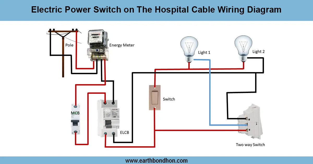
- Input Supply:Input Supply: Phase and neutral from main line.
- DP Switch / MCB: Provides isolation and protection from overload/short circuit.
- Contactor Coil: Connected via DP switch/MCB and control push buttons or timer/relay for automatic control.
- Motor Terminals: Connected to contactor output for safe operation.
- Earthing: Motor frame, contactor, and switches grounded properly.
- Output: Motor starts when the contactor is energized and stops when de-energized, providing reliable and safe operation.
This configuration enables manual as well as automatic control of the motor, which assures protection, convenience, and flexibility.
Testing & Final Adjustments
Connection After wiring, make sure that all connections are tight and insulated. Turn on the DP switch/MCB, test the control circuit with the aid of the push button or timer. When the contactor coil is energized, the motor should start smoothly, and when de-energized, the motor should stop. Check the supply voltage at motor terminals (approx. 220 V -240 V) to confirm proper supply. Safety checks on earthing of checks. Check on any non-normal noise, vibration, or heating. Make sure that push buttons or timer/relay controls work satisfactorily. Label all parts, such as the DP switch, contactor coil, and terminals of motors, and control buttons, so as to be able to identify them easily. Incorporating the right testing makes sure that the motor is working safely, the contactor is working properly, and the system is not affected by any electrical faults.