

Power Socket In 3 Phase Motor Wiring Diagram
Learn how to wire a power socket for a 3-phase motor, including live, neutral, and earth connections for safe and efficient motor operation.

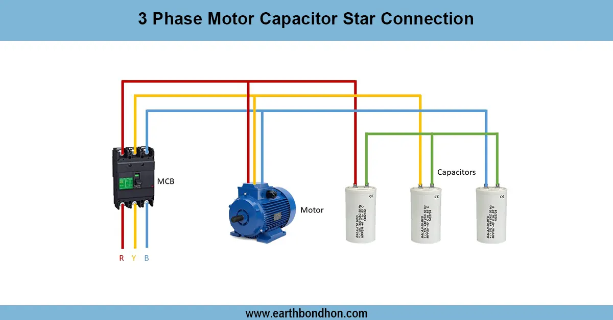
three-phase motor socket setup
A 3-phase motor power socket is a safe connection for industrial motors. Adequate wiring has three phases, and neutral (where necessary), and an earth with protective working devices.
three-phase motor control socket
The power socket wiring of a 3-phase motor is to ensure the motor is connected safely and reliably to the supply. The phase socket terminals are linked to the L1, L2, and L3 lines. It has a neutral connection in case needed by the motor. The earthing is required to be connected to the ground to avoid electric shocks and to ensure equipment safety. The socket and the plug should be rated depending on the motor rating to current, and voltage. The industrial 3-phase motors frequently employ IP-rated sockets to endure the severe conditions. Proper wiring must also have overload fuses or MCB short-circuit protection. Testing is one process done on the voltages of the line, continuity, and proper phase sequence before the connection of the motor. Proper installation will also provide proper start-up of the motor, eliminate problems with phase reversal, and also give the operator safety.
Work & Installation (Input → Output Summary)
- ConnectL1, L2, L3 supply lines to the socket’s phase terminals.
- Connectneutral if the motor is designed to use it.
- Connectearth wire to the socket earth terminal.
- Ensure thesocket and plug rating match the motor current.
- Includefuses, MCBs, or overload protection in the circuit.
- Verifyphase sequence using a phase sequence meter.
- Connect the motor plug to the socket.
- Test motor operation and check for correct rotation.
Testing & Final Adjustments
- Verify all socket terminals are securely tightened.
- Check continuity of live, neutral, and earth connections.
- Measure line-to-line voltages to confirm supply.
- Verify phase sequence to prevent motor reverse rotation.
- Test motor start-up using the socket connection.
- Ensure overload and short-circuit protection devices are functional.
- Inspect wiring for insulation and mechanical damage.
- Confirm the socket is mounted securely and protected from water or dust.
- Perform multiple motor start/stop cycles for reliability.
- Label the socket and circuit for easy identification and maintenance.