3-phase motor contactor wiring
Learn contactor wiring with a holding circuit for motor control using start/stop push buttons, ensuring continuous operation until the stop is pressed.

industrial motor control diagram
Continuous running of motors after the start button has been pressed is done by contactor wiring comprising of holding circuit. It provides reliable and safe usage of the motors in industries with the help of auxiliary contacts, start/stop push buttons, and overload protection.
contactor holding circuit wiring
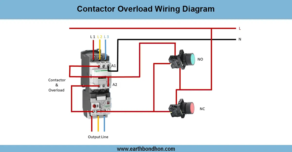
Holding circuit Contactor wiring can be used to keep a load or motor energized even after the start button is released. The system consists of a contactor, start-stop push buttons, an overload relay, and motor connections. On pressing the start button, the contactor coil becomes energized, and in parallel with the start button, the normally open auxiliary contact of the contactor closes. This holding circuit holds the contactor coil energized even after the release of the start button. After pressing the stop button, this interrupts the circuit and de-energizes the contactor, halting the motor. The contactor coil has overload relay protection in series with the contactor coil to cut off the motor in the case of overcurrent. Correct wiring will provide safe and consistent operation of the motor and constant running of the load, rather than continuously holding the start button and overloading. This wiring is common in industrial-applied motors, pumps, fans, and conveyor systems.
Work & Installation (Input → Output Summary)
- Supply Voltage connects to contactor coil and push buttons.
- Start Push Button energizes contactor coil.
- Auxiliary Contact (Holding Contact) closes in parallel with the start button to maintain coil energization.
- Stop Push Button opens the circuit, de-energizing the coil.
- Overload Relay trips if motor current exceeds safe limit, breaking the holding circuit.
- Motor Load runs continuously until the stop button or overload trips the circuit.
Testing & Final Adjustments
- Verify proper insulation and connection of supply, contactor, push buttons, and motor.
- Press the start button; the motor should start and remain running after releasing the button.
- Press stop button; motor should stop immediately.
- Test auxiliary contact to ensure holding circuit maintains coil energization.
- Simulate overload condition to ensure relay trips and de-energize the motor.
- Inspect contactor contacts and terminals for secure connections.
- Confirm earthing for safety and reliability.
- Test repeated start/stop cycles to verify consistent operation.
- Check motor direction and smooth operation under load.
- Record results for future maintenance and troubleshooting.
Frequently Asked Questions - 3-phase motor contactor wiring:
What is a holding circuit?
A circuit that keeps a contactor coil energized after the start button is released.
Why use a holding circuit?
To allow motor or load to run continuously without holding the start button.
Which devices are required?
Contactor, start/stop push buttons, auxiliary contact, overload relay, and motor.
How does it work?
Start button energizes coil, auxiliary contact maintains energization, stop button breaks the circuit.
Is overload protection needed?
Yes, to prevent motor damage during overcurrent conditions.
Can this be used for 3-phase motors?
Yes, widely used in industrial 3-phase motor control circuits.
How to test holding circuit?
Press start button and release; motor should continue running until stop is pressed.
Is earthing necessary?
Yes, to ensure safety and prevent electrical hazards.
Where is this wiring used?
In pumps, fans, conveyors, and industrial motor applications.
Can the holding contact fail?
Yes, if the auxiliary contact is damaged or miswired; regular inspection is required.