Motion Sensor connection
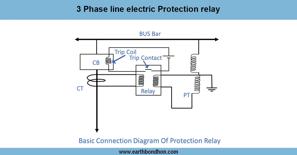
Step-by-step wiring diagram of a motion sensor connected to a light circuit for automatic ON/OFF control based on detected movement.

motion detector light wiring
The wiring of motion sensors simply involves linking the live, neutral and load cables of the motion sensor to power supply and the light bulb so that automatic control of the light is achieved when motion is detected.
Formula & Table Summary:
Line (Live) Input: Supplies power to the sensor.
Neutral: Completes the electrical circuit.
Load Output: Connects to the light fixture.
Earth (Ground): For safety grounding.
Operation: Sensor relay closes load circuit upon detecting motion, turns off after delay.
| Terminal | Connection | Function |
|---|---|---|
| L (Live) | Connects to Line/Live supply | Powers sensor circuit |
| N (Neutral) | Connects to Neutral wire | Completes power circuit |
| Load | Connects to light fixture | Controls light ON/OFF |
| Earth (Ground) | Connects to ground wire | Safety protection |
motion activated lighting wiring
The motion sensor wiring diagram shows the connection between a motion sensor switch and a lighting load to have the light switch ON when it detects any motion and switch OFF after a set delay. The usual connection comprises of line (live), neutral, load to the lighting device, and an earthing point to the earth. The motion sensor is a relay-based device where its internal relay operatively manages the load circuit in accordance to infrared detection. Such an arrangement is highly popular in security lighting, corridors and outdoor settings to save energy or convenience. Appropriate connections and right attachment of terminals give efficient usage and security.
motion sensor connection
| Motion Detected | Sensor Relay | Light Status | Remarks |
|---|---|---|---|
| Yes | Closed | ON | Light turns ON automatically |
| No | Open | OFF | Light remains OFF |