Water level controller wiring
Clear wiring diagram for water level controllers, showing connections to sensors, pumps, power supply, and relays for automatic water level management.

water level controller wiring
Water level controller wiring links sensors that measure the amount of water in a tank to a control unit that delays a pump on or off using relays. With the correct wiring, there is automatic filling or draining and this eliminates overflow and cause of damage to equipment being used and also makes more efficient use of water.
Formula & Table Summary:
Basic logic:
Pump ON when Level < Low; Pump OFF when Level ≥ High
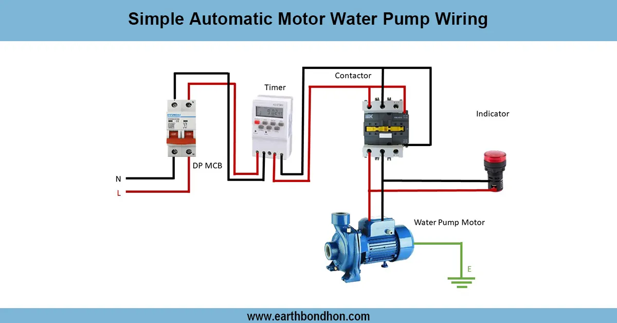
Relay wiring: Coil powered by controller output, contacts switch pump power circuit.
Sensor wiring: Float switch or probe wiring to controller input terminals (normally open/closed depending on type).
Power supply: 230 V AC (typical), live and neutral with earth connection.
Safety: Use fuses, proper insulation, waterproof cables for sensors.
| Component | Connection | Notes |
|---|---|---|
| Power Supply | L, N, Earth to controller | 230 V AC typical |
| Level Sensors | Input terminals on controller | Float switch or probes |
| Relay Coil | Controller output terminals | Activates pump circuit |
| Relay Contacts | Switch pump power line | Normally open or closed |
| Pump Motor | Power supply through relay contacts | Starts/stops per controller |
water level sensor connection
A wiring schematic or water level controller shows the the simplest way of wiring level sensors or float switches to an automatic control unit that can seal a pump or valve to ensure desired water levels in tanks. Normal systems have one or more sensors, which are used to understand when there is low water and high water. Sensor signals are sent to the controller that switches a relay to turn the pump on or off to avoid triggering either an overflow condition or dry running. Wiring of power supply consists of live and neutral connections including appropriate earthing. The pump motor circuit is controlled using relay contacts typically through a contactor or directly (where lower rated than the contractor). Wiring should be in accordance with electrical safety regulations and correct polarity, fuse protection, and waterproofs the sensor wires. The guide assists the Do-It-Yourselfers, the technicians to install some of the reliable water level controllers in home and industrial or agricultural water control.
water level sensor connection
| Low Level Sensor | High Level Sensor | Pump Status | Remarks |
|---|---|---|---|
| Open (Water Low) | Open (Below High) | ON | Pump fills tank |
| Closed (Water Reached) | Closed (At High Level) | OFF | Pump stops |
| Open | Closed | ON/OFF per logic | Depends on controller setup |
Frequently Asked Questions - Water level controller wiring:
What is a water level controller?
A device that automatically controls pump operation based on water level.
How do float switches work in water level control?
They open or close circuits as water reaches preset levels.
Can I wire multiple sensors to one controller?
Yes, controllers often support multiple level sensors for high and low detection.
What power supply do water level controllers need?
Typically 230 V AC, but some use 12 V or 24 V DC depending on model.
How is the pump connected in the wiring?
Via relay contacts controlled by the water level controller output.
Are waterproof cables necessary?
Yes, for sensors submerged in water or exposed to moisture.
Can I install the controller myself?
Only if familiar with electrical wiring and safety; otherwise hire a professional.
What safety precautions should be taken?
Use fuses, earth grounding, proper insulation, and waterproof connectors.
What happens if sensors fail?
The pump may run continuously or stop, risking overflow or dry run.
How to test the water level controller wiring?
Simulate sensor triggers and verify pump response and relay activation.