3-Phase ATS circuit wiring
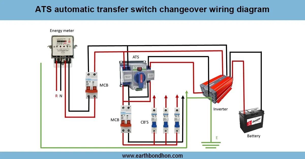
Detailed 3 phase ATS wiring diagram for automatic transfer switch installation to switch power between mains and generator safely and efficiently.

3 phase power transfer switch
A 3 phase ATS circuit contains automated electrical load transfer between mains and generator that uses power conditions to transfer power sources through safe power switch without manual intervention.
3 Phase ATS Circuit Wiring Summary:
Mains Input: 3 phase supply from utility grid
Generator Input: 3 phase backup power supply
Load Output: Connected to critical load circuits
Control Circuit: Monitors voltage/frequency, controls switch mechanism
Protection: Circuit breakers and relays for safe switching
automatic mains transfer switch
An automatic transfer switch (ATS) in a 3 phase wiring circuit permits automatic transfer of power availability between an active grid and a secondary generator. The ATS is the kind that monitors mains voltage and frequency and in case of power failure or abnormality, it automatically switches a load to generator supply. The ATS re-switches to mains supply once the mains power is re-established. Connection to provide three phase mains input, generator input, load output, and control circuits to control the transfer mechanism should be properly wire the ATS. Safety switches are incorporated by the use of a protection device that includes circuit breakers and relays. ATS wiring maintains continuous power to loads in Industry, commerce or residential areas that are vital.
3 phase generator switch wiring
| Terminal | Connection | Function |
|---|---|---|
| Mains L1, L2, L3 | Connected to ATS mains input | Utility power source |
| Generator L1, L2, L3 | Connected to ATS generator input | Backup power source |
| Load L1, L2, L3 | Connected to ATS load output | Supplies power to load |
| Neutral | Common neutral for all inputs and load | Completes the circuit |
| Control Circuit | Monitors voltage and controls switching | Ensures automatic power source changeover |