Single Phase Motor Changeover Connection With Diagram
Learn single-phase motor changeover connection with wiring diagram, step-by-step installation, DP switch or MCB selection, and safe operation for home motors.

electrical socket wiring
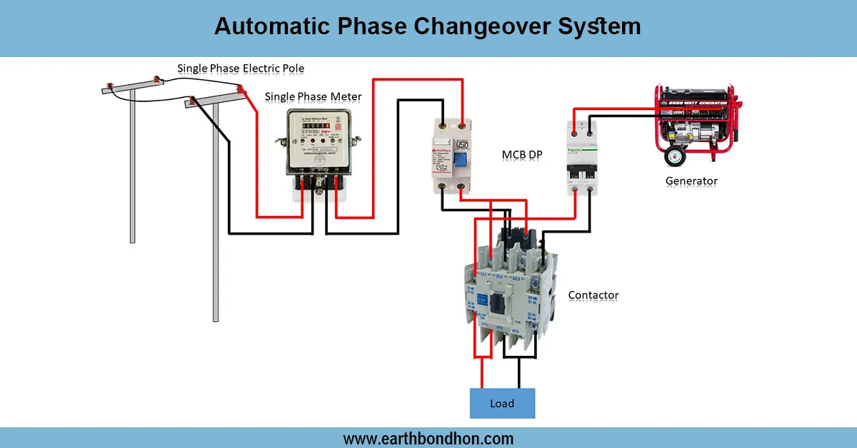
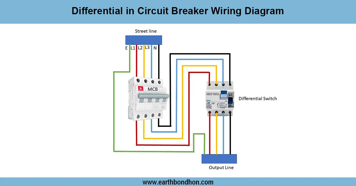
A single-phase motor changeover connection diagram illustrates the connection of the main supply and the alternative supply to the motor via a DP switch, with the supply switching controlled without interrupting the motor.
single phase motor changeover wiring:
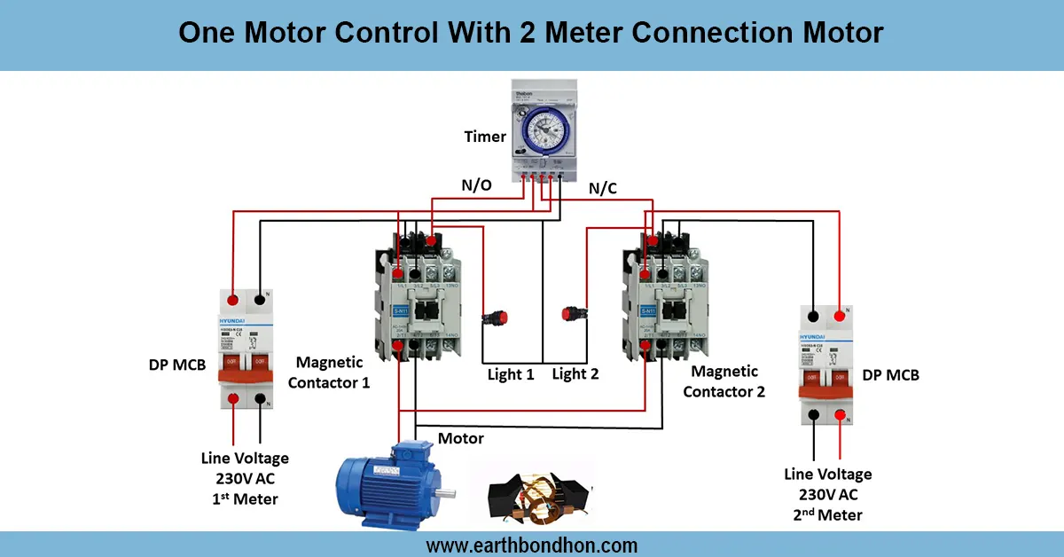
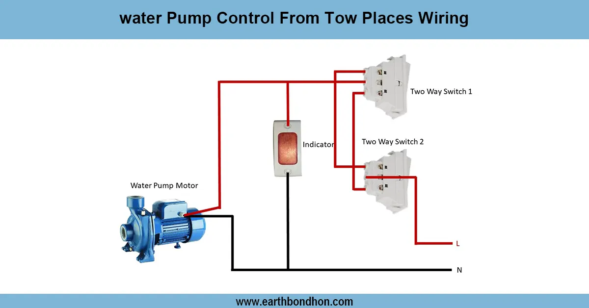
Single-phase motor changeover connection enables a motor to be operated using two or more sources of supply, or through two circuits, which is flexible and safe. The power supply to the motor is usually switched on and off by a DP switch or an MCB. Here, the changeover switch receives incoming phase and neutral on the main supply, and turns power to the motor or to some other source. The motor terminals are then connected as per the instructions of the manufacturer, and good earthing is done to eliminate electrical hazards. This type of wiring installation is commonly used in pumps, fans, or other small equipment requiring alternate power, or isolation to allow the equipment to be inspected. An understandable wiring diagram would ensure the electricians and homeowners install the changeover system properly without causing any harm to the motor or posing any safety hazard.
Work & Installation (Input → Output,)
- Input Supply: Phase and neutral wires from main power line.
- Changeover Switch: DP switch or changeover MCB is installed; it directs power to the motor from either the main or alternative supply.
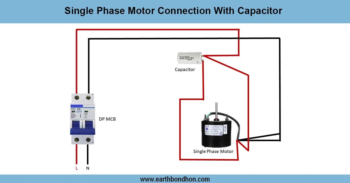
- Motor Terminals: Connect according to the wiring diagram, ensuring correct rotation direction.
- Load Protection: Overload protection or motor starter may be included in series.
- Earthing: Motor frame and switchboard are connected to earth.
- Output to Motor: Motor receives phase and neutral via changeover switch, enabling safe and controlled operation.
This construction makes a safe changeover, eliminates short circuits, and does not require de-energizing the main supply.
Testing & Final Adjustments
Check all terminals after wiring to make sure that they are connected. Make sure that the supply is correctly alternated on the DP switch between the main and alternative circuits. Check the operation of the motor with each supply source, ensure that it turns properly and does not produce any noise. In case of overloading, the motor starter or MCB is supposed to trip. Measure the voltage at the motor connections to ensure that it is a proper supply. Make sure that earthing is in place and operational, and insulation is intact. Any loose wires must be tightened, and all the metal must be grounded properly. Label the DP switch and motor connections so that they can be readily identified. Following these tests, the system provides safe, efficient, and reliable running of the motor having controlled changeover capability.