

Digital Timer Switch wiring Diagram
Learn how to wire a digital timer switch for lights, fans, and appliances. Step-by-step input-to-output wiring, testing, installation, and safety explained.

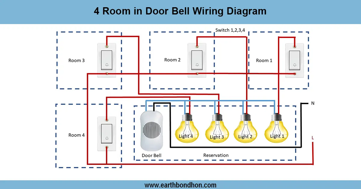
timer switch for lights wiring
Link live wire to timer input, output to load, neutral to load, and timer. ON/OFF times to automate electrical circuits.
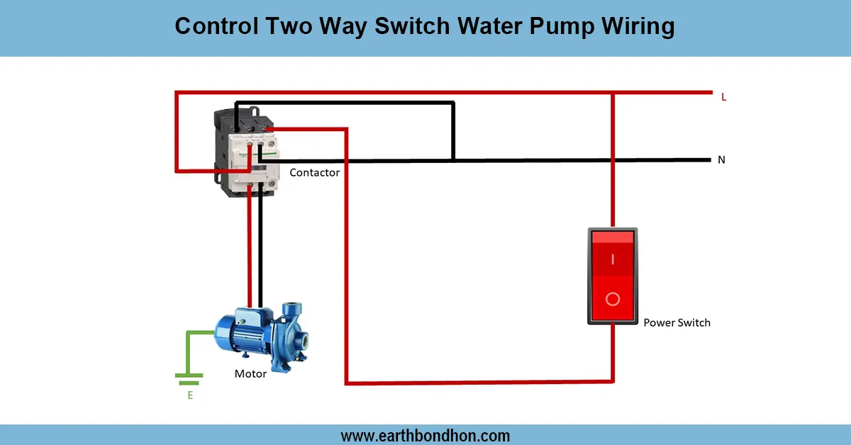
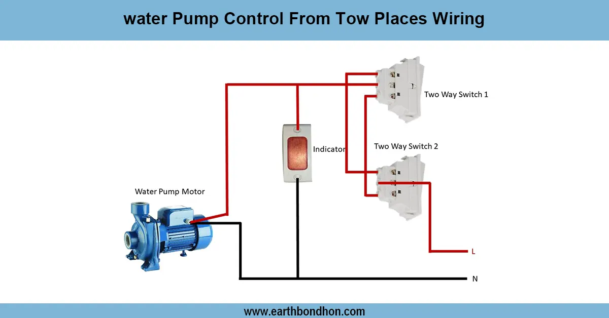
water pump timer switch wiring
A digital timer switch electrical wiring system is applied, which controls loads such as lights, fans, water pumps, and appliances at specified times automatically. The timer switch is programmed to switch ON and OFF cycles and save on energy consumption and convenience. The digital timer operates on an internal relay to operate the circuit according to the schedule, as opposed to the manual switches.
In wiring, the phase (live) input is wired to the supply terminal of the transformer,,r and the output is wired to the load. There is also the provision of neutral and earth connections to operate safely. As the programmed time comes, the timer relay opens and provides power to the load and closes when the cycle is finished.
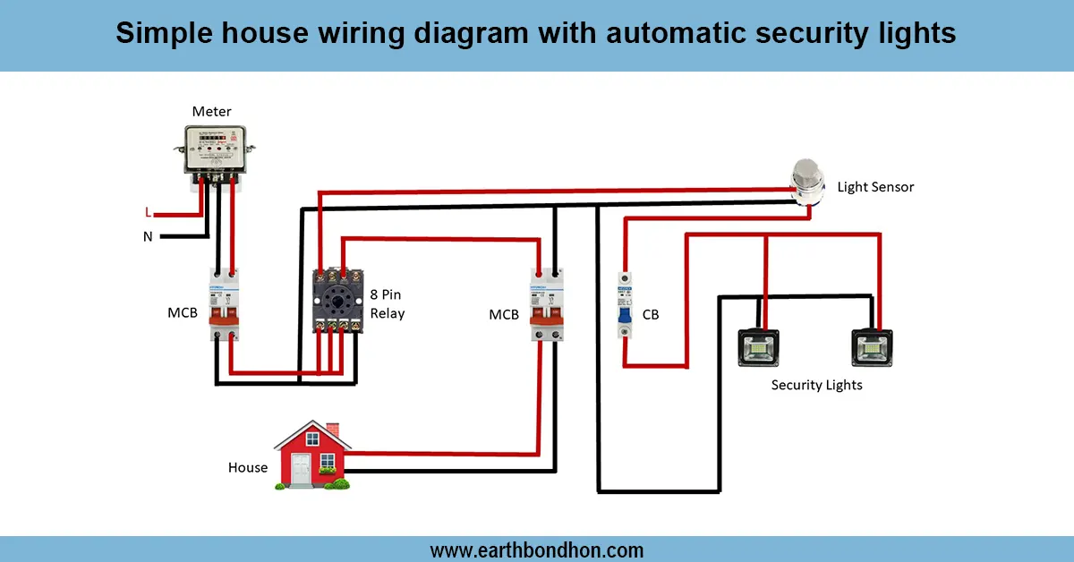
This is the setup used in most cases of home automation and street lights, in agricultural waterpumps, and in industrialmachinesis and this offers safety, efficiency, and reliability. To ensure greater protection, the timer switch is suggested to be used together with MCB/RCCB.
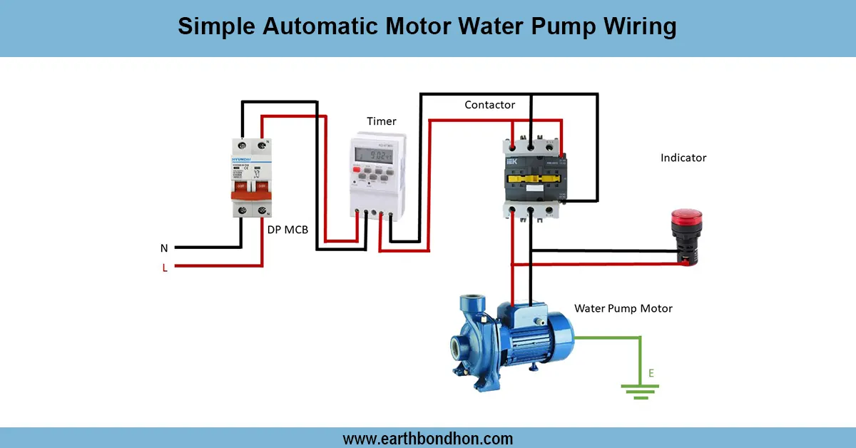
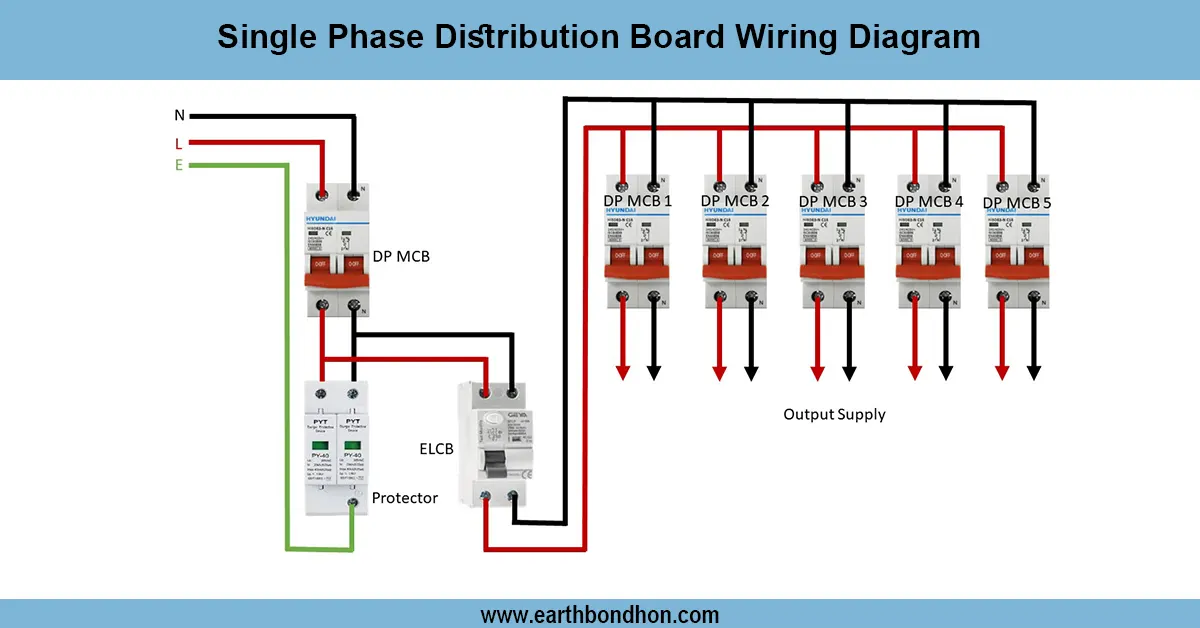
Work / Installation (Inputs → Outputs)
Input: Main supply → MCB/RCCB → Digital Timer Switch.
- Connect phase (L) to the input terminal of the timer switch.
- Connect neutral (N) to the timer’s neutral terminal.
- Take the output (L-out) from the timer and connect it to the load (light, fan, or pump).
- Connect neutral directly from the supply to the load.
- Ensure proper earth connection for safety.
Output: When the programmed time is reached, the timer relay energizes, supplying phase to the load. The load runs automatically until the timer switches OFF.
Testing & Final Adjustments
Once you have wired it, supply it and test the timer by programming it to short ON/ OFF cycles. Verify that the output supplies the load with power only at the programmed time. Meathe ssured the oltage load side to verify operation. Check connections to ensure tightness, check phase and neutral polarity, and bond earth. Test MCB/RCCB trip is used to check safety. Modify the timer settings to include daily/weekly adjustments, manual override, and random mode.
Neatly wired with ferrules, cable ties, and terminal covers. In the case of inductive loads (motors/pumps), take the time to drive a contactor so that the timer relay is not overloaded. This makes the digital timer switch reliable, less manual work, and more economical.