single phase submersible motor starter wiring
Learn submersible pump wiring with magnetic contactor, overload relay, MCB, and float switches for safe and automatic water pumping in tanks and borewells.

single phase submersible motor starter wiring
The submersible water pump wiring diagram represents the connection of the AC supply, MCB, magnetic contactor, overload relay, float switches, and motor to initiate the safe automatic running of the water pump.
submersible motor starter connection diagram:
There is a magnetic contactor water pump that operates a submersible water pump safely and automatically with the help of control devices. To prevent short-circuiting and overloading of the motor, the magnetic contactor is a remotely controlled switch to manage high current. The wiring consists of an AC supply, an MCB, a Magnetic Contactor, an Overload Relay, a Pump Motor, and Float Switches. Float switches automatically turn off/on the pump according to the water levels. Trip a relay of overcurrent to prevent overloading of the motor. An IS controlled by a low-voltage float switch or timer signals can be operated easily in an automatic manner through the magnetic contactor. The earthing must be done properly to be safe. Adherence to the wiring scheme will provide a hassle-free flow of electricity in the motor, resulting in energy efficiency and a long lifespan of the motor. The application of this setup is common in residential, agricultural, and commercial water pumping systems in the management of water supply on an automated basis.
Work & Installation (Input → Output,)
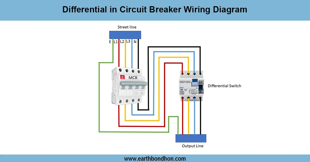
- AC Supply: Connect single-phase or three-phase supply to MCB input.
- MCB/Main Breaker: Provides circuit isolation and short-circuit protection.
- Magnetic Contactor: Acts as the main switch to control high motor current.
- Overload Relay: Connected in series with the contactor to protect the motor from overcurrent.
- Float Switch Connection: Low/high water level float switches control the coil of the magnetic contactor for automatic ON/OFF.
- Pump Motor Connection: Contactor output terminals connect to the submersible pump motor.
- Earthing: Ground the control box, contactor, and pump for safety.
- Operation: Float switches energize or de-energize the contactor coil to start or stop the pump automatically.
- Output: Safe, automatic pumping with overload and dry-run protection.
Testing & Final Adjustments
Wire after Wiring input voltage and energize the control box. Test the low water level to ensure that the magnetic contactor energizes and initiates the motor. Check for a proper smooth rotation and the right direction of the motor. Test to simulate a high water level, this way the contactor will automatically de-energize and the motor will automatically stop. Check all the wiring connections to ensure that they are tight, insulated, and that the earthing is secure. Test the overload relay by simulating the overcurrent to make sure that it trips. Switch the MCB on to ensure that it isolates the circuit. Test various cycles to have good automatic functionality. Label all connection points in the terminals, float switch, and contacts, so that they are easily maintained. Correct testing will eliminate the possibility of damaged motors, dry runs, and electrical accidents. Periodic checking of the contactor, float switches, overload relay, and MCB will result in long-term reliability, safety, and economical energy. Adherence to the wiring scheme will ensure that the electrical safety standards are adhered to and that the submersible water pump will work automatically.
Frequently Asked Questions - single phase submersible motor starter wiring:
What is a magnetic contactor?
A remotely controlled switch that handles high current for motors.
Why use a magnetic contactor in submersible pumps?
To safely control high current motor operation automatically.
Which starters are used?
Direct On Line (DOL) or Star-Delta starters, controlled by the contactor.
Why use float switches?
To automatically start or stop the pump based on water level.
Is overload protection necessary?
Yes, to prevent motor damage from overcurrent.
How is the motor connected?
Through contactor output terminals to the submersible motor.
Is earthing required?
Yes, for safety of motor, contactor, and control box.
What is MCB used for?
To isolate the circuit and protect against short circuits.
Can the pump run automatically?
Yes, float switches control the contactor coil for automatic start/stop.
Why follow wiring diagram?
Ensures safe, reliable, and efficient motor operation.