Run two motor in selector switch
Learn to run two motors safely with a selector switch, including wiring, overload protection, and a control circuit for industrial or home applications.

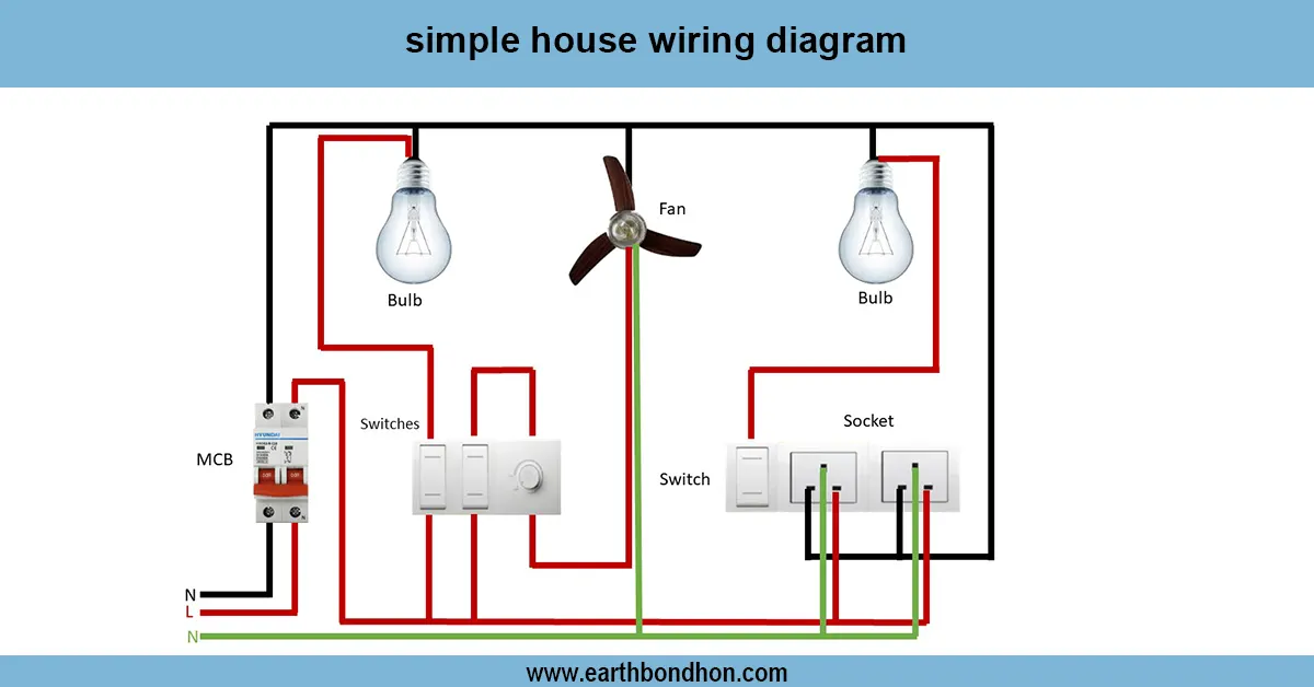
electrical socket wiring
A selector switch provides a very easy and dependable manner to operate two motors with one control interface. The wiring of the switch with two magnetic contactors, one per motor, incorporating overload protection, enables only one motor to be on at a time, based on the position of the switch. This arrangement is optimal in a situation where there is a need of having a backup motor, say in a pump set-up or an industrial fan, where the deciding switch enables you to select which motor is energized and leave the other off. Properly wired and with protective parts, this dual motor control by a selector switch is efficient to work, requires less power waste, and is easily maintained. This method is ideal when users require a low-cost solution, but without complex automation, high levels of reliability, and ease of control.
dual motor changeover switch wiring:
A single control panel can be used to control two motors using a selector switch. The switch connects one motor when it is in a certain position and disconnects the other motor so that they are not able to run concurrently. The wiring would be to the main supply to the common terminal of the selector switch, and individual lines of output of each switch position to the respective motor or motor contactor. Each motor should have overload protection (MCBs or fuses, etc.). Start/stop can be added with the help of push buttons. Correct installation would guarantee safe operation, proper choice of the motor, and overcurrent protection. Testing includes: ensuring that a switch position is selected to operate only one motor and ensuring that overload protection works properly. This is suitable in the industrial, agricultural, or domestic system where the motors are connected to one control panel.
Work & Installation Summary
- Connectline supply to the common terminal of the selector switch.
- Run separateoutput wires from each switch position to motor terminals or contactors.
- Connectoverload protection (MCB/fuse) in series with each motor line.
- Install optionalstart/stop push buttons for each motor.
- Label switch positions for each motor.
- Verify correctphase sequence for three-phase motors.
- Mount the selector switch and motors securely.
- Test each switch position: only the selected motor should run.
Testing & Final Adjustments
- Checklive, neutral, and earth connections.
- Verify that the selector switch energizes only the intended motor.
- Confirmoverload relays or fuses work correctly.
- Observe motor rotation and ensure proper load handling.
- Inspect wiring for tight connections and insulation.
- Test multiple switch cycles for reliability.
- Label switch and motors for maintenance reference.