


Series Circuit for light wiring
Learn series circuit wiring diagram with step-by-step guide, working principle, installation process, testing, and safety tips for beginners.

series circuit wiring diagram
A series circuit wiring diagram is a type of circuit that joins parts together in one direction so that the current moves in the same direction. When one of the lamps goes out, the entire circuit goes dead.
series lamp wiring connection
A series circuit wiring diagram represents an end-to-end connection of electrical component in a single circuit in such a way that the same current passes through every part of the circuit. In this kind of relationship, the output of one machine is fed to the input of another. Its greatest benefit is that it is simple to install. But when one device is malfunctioning, the whole circuit will cease. Decoration lights, Christmas lights, or little learning projects typically use series circuits. To make a series wiring, the order of connection is as follows: The supply to the first lamp, to the second lamp, to the third lamp, etc. Lastly, the neutral of the power source is connected with the last lamp.
Work / Installation (Inputs → Outputs)
- Input: Line (phase) and neutral from supply.
- Output: Lamp connection.
steps:
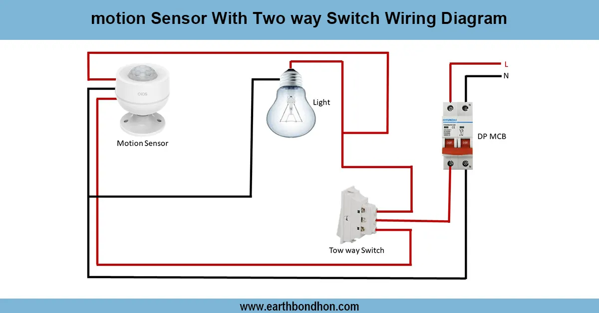
- Connect the phase (line) wire from the supply to one terminal of the switch.
- Connect a wire from the other terminal of the switch to the phase terminal of the lamp.
- Connect the neutral wire directly from the supply to the neutral terminal of the lamp.
- Connect the earth wire to the lamp holder or metal body for safety.
Now, when the switch is turned ON, the current flows through the lamp and it glows.
Testing and Final Adjustments
Check after wiring- all devices have been connected end-to-end. Turn on the power supply and test. When one lamp is lit, light all the lamps. When one of the lamps is faulty or switched off, the whole circuit will be switched off. This is the key drawback to a series connection. Make sure that connections are tight and insulated. Install the appropriate rating of lamps. It is always a good practice to load it with a small weight before it is fully used.
Frequently Asked Questions - Series Circuit for light wiring:
What is a series circuit wiring?
It is a circuit where components are connected in a single path.
Where is series circuit used?
In decorative lights, toys, and learning projects.
What happens if one bulb fails in series circuit?
The whole circuit stops working.
Does current remain same in series circuit?
Yes, the same current flows through all components.
What is the disadvantage of series circuit?
If one device fails, the entire circuit stops working.
Is voltage same across all bulbs in series?
No, voltage divides across components.
Can fans be connected in series?
No, heavy loads like fans should not be connected in series.
What is an example of series connection?
Christmas lights are a common example.
How to connect two bulbs in series?
Phase to first bulb, then link to second bulb, and finally to neutral.
Is series circuit safe for home wiring?
No, parallel wiring is safer and commonly used at home.