Electric Energy Meter Wiring
Learn house wiring with energy meter connections, input-output supply, MCB, earthing, and safety steps explained with diagram.

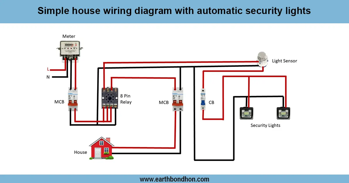
energy meter house wiring diagram
Energy meter in house wiring diagram: a circuit connecting the utility supply to the house circuits. The meter is connected to the input phase and neutral wires, and the outputs are connected to the main switch, MC, B, and distribution board.
single phase energy meter connection
A house wiring diagram energy meter illustrates the way electricity flows into the house via the supply line through the meter and out to the household circuits. The energy meter measures the amount of power that all lights, fans, and appliances use. Phase and neutral utility pole wires are normally connected to the input terminals of the meter. At the output side of the meter, the phase is connected to the main switch/MCB, and the neutral is directly connected to the distribution board. Protection is given by earthing. Improper meter installation entails inappropriate electricity billing and usage. Utilizing common wiring techniques, safe connections, and protective equipment helps to avoid such risks as overloading or electric shock.
Work / Installation (Inputs → Outputs)
The installation of an energy meter starts with the utility (phase and neutral) input lines. They are hooked up to the input terminals of the meter. The output side offers phase and neutral. The phase is wired to a main switch or MCB, and then directly to the distribution board, but the neutral is wired to the DB. Circuit breakers then send the electricity to lights, fans, sockets, and appliances via the DB. The electricity provider must provide good earthing and meter sealing. Any used wiring has to be of standard cable sizes and in accordance with local regulations.
Testing & Final Adjustments
After the wiring has been done, it is then tested to make sure it is operating safely. Inspect the tightness of the check meter terminals, check the input and output connections with a checker, and verify that the phase is not inverted. Turn the MCB on and ensure the supply of electricity to the distribution board is working correctly. Check individual circuits, switches, and sockets to ensure that they do not spark off or overheat. Check earthing with a continuity test. When loads are on, the energy meter should indicate the correct readings. Last stage modifications involve screw tightening, insulating bare wires, labeling circuit breakers, and sealing the meter in accordance with electricity authority requirements. This ensures long-term security and appropriate power measurement.