Two way Switch Water Pump Wiring
Learn single-phase motor control from two places: wiring with diagrams, DP switch/MCB protection, safe operation, and step-by-step installation for home motors.

electrical socket wiring
The wiring diagram of a single-phase motor control at two places is used to illustrate how a motor can be safely operated at different locations with two SPDT switches or a DP switch system with isolation and overload protection.
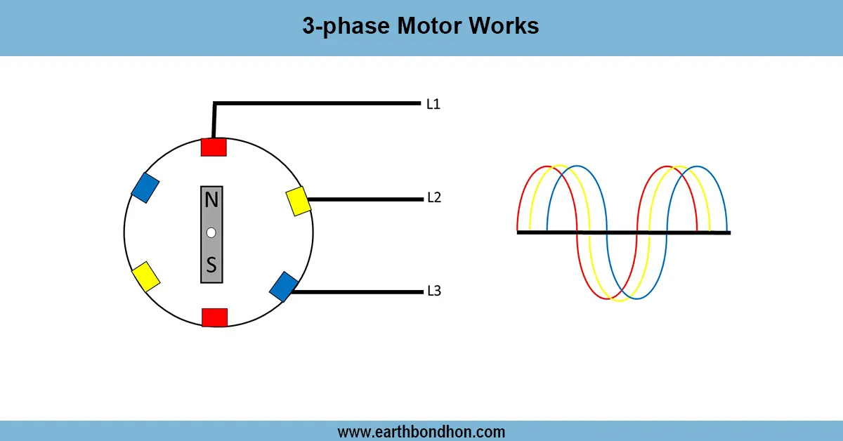
single phase motor control from two places:
Two locations. Single two-phase motor control with two locations allows the operation of a motor at two locations by using two SPDT (single-pole double-throw) switches, or a DP switch system. The neutral and the incoming stage are linked with a DP switch or MCB, which guards the circuits and the motor. These motor terminals would be wired up following the wiring diagram, and the two control points would be wired in such a way that when switched to either location, the motor would start or stop without causing harm to itself. All switches and all frames of motors are given proper earthing to ensure them to be safe. Such a system is typically applied to the water pumps, ceiling fans, or small machines where the motor operation is required at several points. A well-defined wiring plan provides proper installation, thereby avoiding short circuits, reverse current, and damaging the motor, and besides making it easily and safely accessible.
Work & Installation (Input → Output,)
- Input Supply: Phase and neutral from the main line.
- Main DP Switch / MCB: Provides isolation and overload protection.
- Motor Terminals: Connect the main winding to supply via control wiring.
- Control Points: Two SPDT switches wired to allow ON/OFF operation from either location.
- Earthing: Motor frame and switches grounded for safety.
- Output: Motor can be started or stopped from both control points safely and reliably.
This design provides flexibility of operation, convenient motor control, and safe maintenance isolation.
Testing & Final Adjustments
Once wired, go through all connections, making sure that they are tight and well insulated. Switch on the main supply or DP switch, or MCB, and perform a test of every control point separately. When the motor is switched, it should switch off when the switch occurs at either end. Check volts at motor terminals (220 V -240 V). Ensure that earthing connections are safe and operational. Measure SPDT switches with no short current or reverse current. Label control points and MCB so that they can be easily identified. Check on loose wires, damage to insulation, and exposed terminals. Once these checks are done, the motor control system will be reliable, can be operated at two points, and isolate the motor and the user against electrical hazards.
Frequently Asked Questions - Two way Switch Water Pump Wiring:
What is two-place motor control?
It allows a single phase motor to be operated from two separate locations safely.
Which switches are used?
Two SPDT switches or a DP switch arrangement are typically used.
Is earthing necessary?
Yes, the motor frame and switches must be properly grounded.
Can MCB be used instead of DP switch?
Yes, a double pole MCB can isolate both phase and neutral safely.
How to wire two control points?
Use two SPDT switches connected according to the wiring diagram.
Will motor run if one switch fails?
Yes, the other switch can still control the motor safely.
What is the supply voltage?
Typically 220V–240V single phase AC.
How to test wiring?
Switch ON/OFF from both points and check motor operation and voltage.
Can it be used for water pumps?
Yes, commonly used for pumps, fans, and household motors.
What is the advantage of two-place control?
It provides convenience, flexibility, and safe operation from multiple locations.