Auto Manual Selector Switch Wiring
Learn electrical control scheme wiring with a selector switch for controlling motors, lights, or machinery safely and efficiently in industrial and commercial setups.

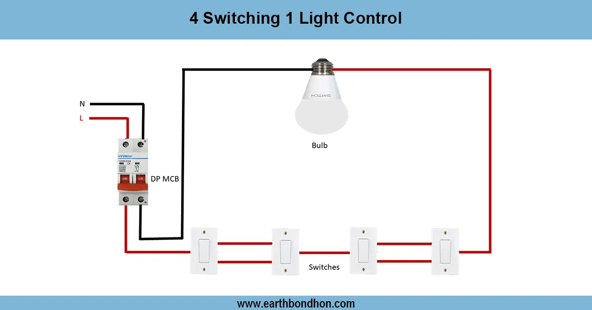
machinery control electrical diagram
In electrical control schemes, selector switches enable operators to choose various operating modes without incurring much loss. Proper wiring can guarantee proper operationality of contactors, relays, and indicator lamps, and the avoidance of faults in the motors or electrical accidents.
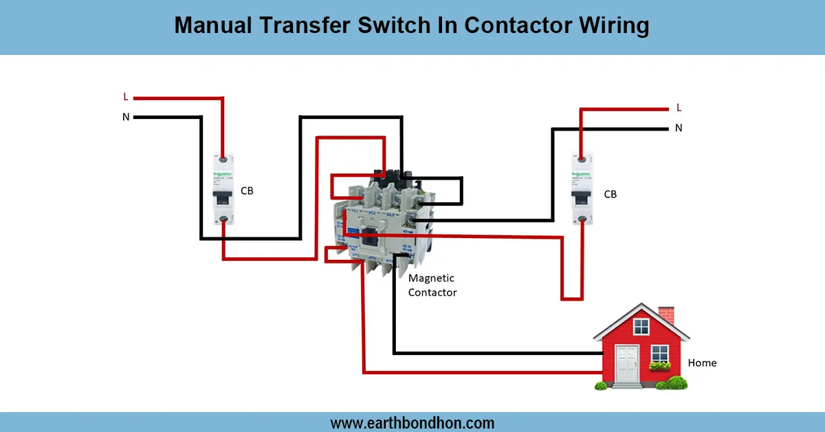
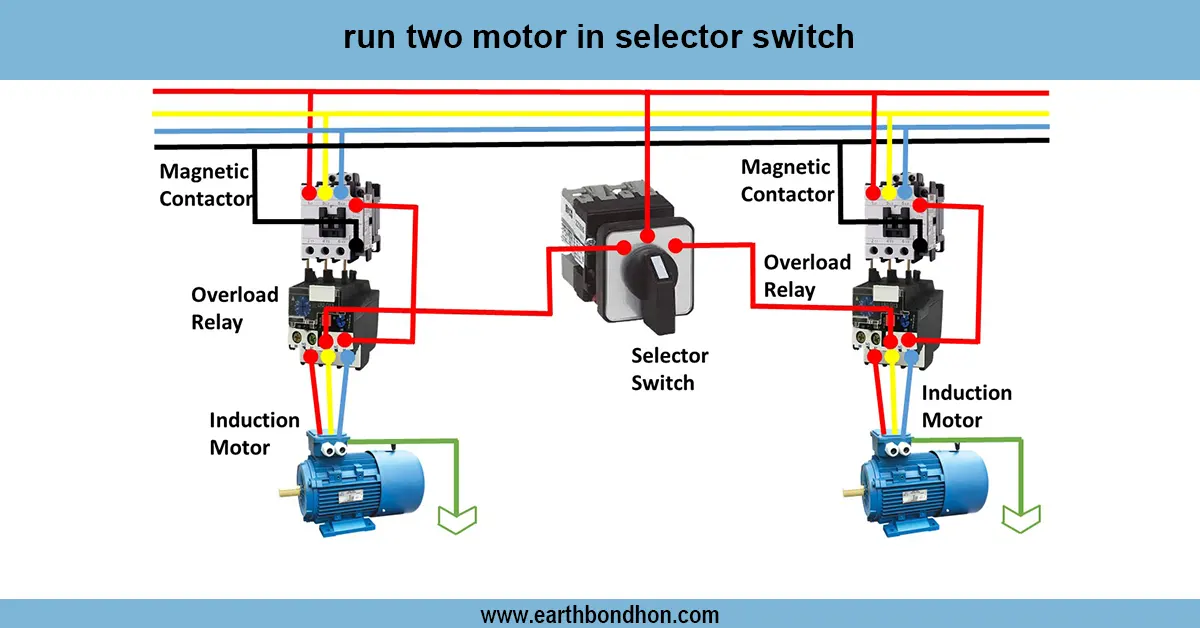
motor control with selector switch
Electrical control scheme, which has a wiring of a selector switch, can be used to make the operator select various operational modes like auto, manual, forward, reverse, or off position. The control circuit is linked to the selector switch and thus makes contactors, relays, and indicator lamps energized in accordance with the selection switch. In a motor control circuit, the choice of the selector switch may be used to switch forward or reverse rotation, start/stop, or manual/automatic. Correct wiring provides safe operation, avoids short-circuit, reversal of phases, and wrong rotation of the motor. The scheme is usually fitted with contactor coils, overload relays, push buttons, fuses, and indicator lamps, all interconnected in line with the switch position in the selector. Testing is conducted on the functionality of the selector switch, which includes ensuring the change of control outputs, the reaction of the motors on the chosen modes, and the work of the safety devices. This type of wiring is common in industrial motor control panels, automated machinery, and production line equipment.
Work & Installation (Input → Output Summary)
- Incoming Supply connects to control circuit via fuses or breakers.
- Selector Switch selects operating mode (manual/auto, forward/reverse, off).
- Contactor Coils energize according to selector switch position.
- Push Buttons may be used for start/stop operations.
- Overload Relays protect motors from excessive current.
- Indicator Lamps display operational status based on selector switch.
- Proper wiring ensures safe control, correct motor operation, and mode indication.
Testing & Final Adjustments
- Verify correct wiring of selector switch contacts to control circuit.
- Test each position of the selector switch; ensure proper output to contactors and relays
- Test forward/reverse motor operation; check rotation direction.
- Test start/stop push buttons for correct control.
- Check indicator lamps light according to selected mode.
- Inspect wiring terminals for secure connections and proper insulation.
- Test overload relay operation by simulating overcurrent.
- Ensure no short circuits or unintended energizing of circuits.
- Repeat switch position tests for reliability.
- Record test results and operational parameters for documentation.