Automatic phase changeover wiring
Learn automatic phase change over system wiring and installation for seamless power transfer, overload protection, and safe operation between multiple phases.

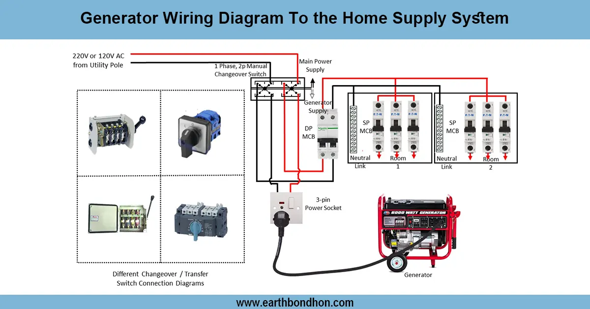
phase changeover wiring diagram
An automatic phase change over system makes sure that power is not lost, by measuring current in more than one stage of supply and automatically switching the load to the stage available. It is common in 3-phase power supply homes, offices, and industrial facilities to avoid damage to equipment in the event of a phase failure or imbalance. The system has phase-sensing relays, contactors, and an automatic changeover controller that senses phase failure and switches the load to a sound phase automatically without human intervention. The correct wiring and installation would ensure that the process works safely, without downtime, and guard against electrical appliances from phase faults.
electrical changeover panel
The Automatic Phase Change Over System is created to provide a continuous power supply by detecting the voltage of several phases and switching the load to one of the healthy phases when a phase is faulty. This system is frequently applied in residential, commercial, and industrial applications to a three-phase power supply to prevent damage to motors, compressors, and vulnerable electronics due to the loss of phases or due to phase imbalance.
The system comprises a phase-sensing relay, contactors, and a changeover controller. The incoming three-phase supply is nascent to the controller, which continuously measures each phase. In case of failure of a phase or a voltage in the phase going beneath a specified safe level, the controller switches the contactor to switch the load to a different healthy phase. As soon as normal voltage is reinstated system transfers to the original phase.
The correct wiring, earthing, and other protective equipment, such as MCBs and RCCBs, must be used to ensure safety and
dependability. This automatic phase changeover system has removed any human intervention requirement and minimized
downtime, which guarantees continuous, safe, and efficient power delivery to all the equipment that is connected.
Work / Installation (Inputs → Outputs)
In automatic phase changeover, the incoming three-phase supply is connected to the phase changeover controller panel. Each stage undergoes the voltage-sensing relays that constantly check the phase voltage. When the phase goes dead or the voltage falls below a safe level, the controller goes off to the contactor, which, in turn, closes the load to another healthy phase. The controller output is linked to the distribution board, which provides power in the building. Overload protection is provided using proper protective devices such as MCBs, RCCBs, and fuses. Installation must be carefully wired with relays, contactors, and input/output terminals, and earthing must be well done to be safe. Such a system offers an uninterrupted power supply, protection to sensitive appliances, and removal of manual operation in case of failure in phases.
Testing & Final Adjustments
The automatic phase changeover system needs to be wired, with testing being a key step. First, verify the voltage in all three phases and make sure that they are connected to the controller. To test whether the system automatically balances load by a healthy phase when one phase is disconnected, simulate a phase failure by disconnecting a phase. Monitor the switching time, voltage, and current values so that it is functioning smoothly without flickering or overload. Test all MCBs, relays, and contactors to suitably respond; earthing must not be missing. Label terminals and phases to assist with maintenance. Check that the load is re-connected to the original phase when normal voltage has been reinstated. Last-minute adjustments ensure acceptable and safe, continuous power flow, ensuring that motors, compressors, and delicate electronics are not damaged by phase failure.