submersible Pump Wiring Diagram
Learn single-phase submersible motor wiring, including capacitor connection, DP switch/MCB, earthing, and safe installation for pumps in domestic and small-scale use.

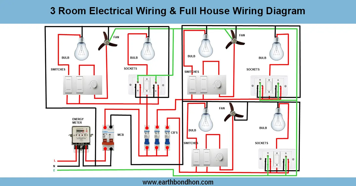
submersible pump wiring diagram
A one-phase submersible motor wiring diagram includes the way to wire the DP switch/MCB, capacitor, and motor terminals to provide safe starting, running, and overload protection.
submersible water pump wiring connection:
A single-phase submersible motor is commonly used with domestic water pumps and small irrigation systems. Wiring is done well to ensure the safety of operation and prevent damage to the motor. The neutral and phase are linked by an isolation and overcurrent protective DP switch or MCB. A phase shift is created with the help of a capacitor, such that the motor is able to start and operate efficiently. The motor cable is properly insulated and waterproofed and connected to the pump motor. To avoid electric shock, earthing cannot be ignored. In the wiring diagram, there are evident connections of the DP switch/MCB, the capacitor, the submersible motor terminals, and earthing. Sticking to the diagram is a guarantee of a proper start, operation, and automatic security of the pump. This installation offers an effective supply of water, energy efficiency, and helps to prevent electrical faults. Correct installation, earthin, and testing are important in the safe use and longevity of the motors.
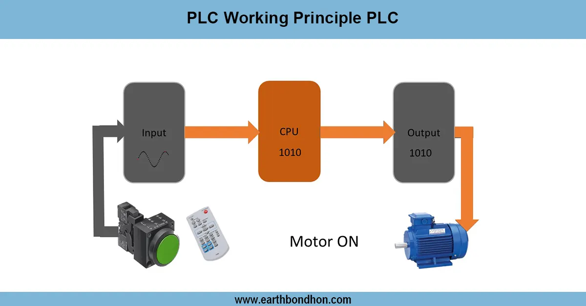
Work & Installation (Input → Output,)
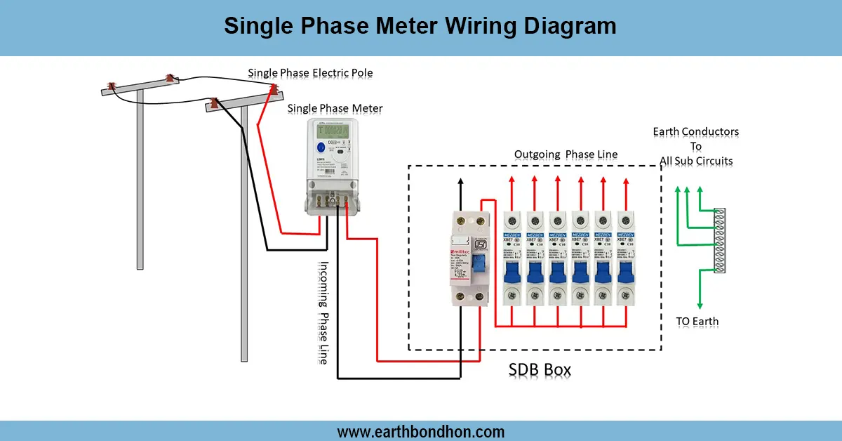
- Input Supply: Single-phase 220–240V AC via DP switch or MCB.
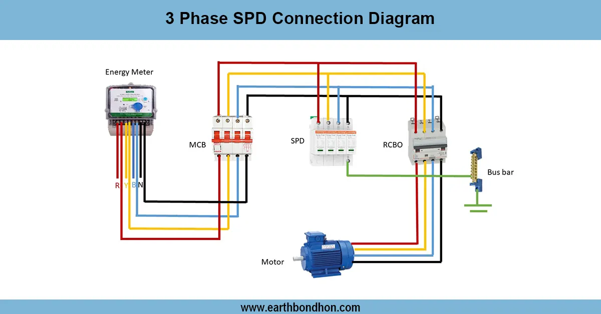
- DP Switch / MCB: Provides isolation and overcurrent protection.
- Capacitor: Connected in series with one motor terminal to create a phase shift for starting.
- Motor Terminals: Two terminals connect to supply; third terminal via capacitor.
- Earthing: Motor body and pump frame grounded properly.
- Output: Motor starts and pumps water efficiently; stops automatically if overload occurs.
This relationship provides the single-phase submersible motors to operate safely, efficiently, and reliably.
Testing & Final Adjustments
Wire Once the DP Switch/MCB has been wired, turn it on and note the motor and see it start. Make sure that the pump begins gradually and with no more than normal speed. PIW measuring between the terminal of the motor (~220 V–240 V) and the capacitor is in place. Check waterproofing and cable insulation to allow ingress of water. Safety of operators: Test earthing continuity. Test the pump by operating it for several minutes at normal load and watch to see whether it overheats or whether it is operating abnormally. Label the DP switch, the capacitor, and the motor cable to be easily identified. General testing is necessary to make sure that the submersible motor runs safely, and will not be damaged by overloading or loss of phase, and to increase the life of the pump. This is the most effective way to ensure that there is a reliable supply of water to domestic or small-scale irrigation systems and that the standards of electrical safety are observed.
Frequently Asked Questions - submersible Pump Wiring Diagram:
How is a single phase submersible motor connected?
Via DP switch/MCB, capacitor, and proper phase/neutral wiring to motor terminals.
What is the role of the capacitor?
Creates a phase shift for starting and running the motor efficiently.
Is earthing required?
Yes, motor and pump frame must be properly grounded.
Which switch protects the motor?
DP switch or MCB protects against overload and short circuit.
Can I connect directly to mains?
No, always use DP switch/MCB and follow wiring diagram.
What supply voltage is used?
Typically 220–240V single-phase AC.
How to test after wiring?
Switch on supply, check smooth starting, running, and no overheating.
Can it run continuously?
Yes, if installed and protected properly according to wiring diagram.
What happens if capacitor is wrong?
Motor may fail to start or run inefficiently and overheat.
Why follow wiring diagram?
Ensures safe operation, prevents motor damage, and extends pump life.