Automatic Transfer Switch Wiring Diagram
Learn ATS automatic transfer switch wiring, working, and installation for safe changeover between the main power supply and the generator backup.

ATS automatic transfer switch
An ATS (Automatic Transfer Switch) is a device that is utilized to automatically switch the supply of power between the main utility line and a backup generator whenever a power failure happens. It removes the manual switching and provides a flowing power supply to homes, offices, and industries. The ATS wiring diagram illustrates the relationship of connecting the main supply and generator to the switch that will subsequently supply the output to the distribution board. As the main power goes dead, the ATS will divert to the generator, and when it returns, it will be diverted back to the utility power in a safe manner.
automatic transfer switch connection
An ATS (Automatic Transfer Switch) is a key device that is necessary to ensure that there is power at all times by changing between the main utility line and a backup generator when power goes off. The ATS keeps an eye on the voltage of the main supply, and in the event of a failure, it sends a signal to the generator and transfers the load without any interruption. When the utility supply is re-established, the ATS returns to the main line and flips off the generator, so that there is no interruption in supply.
The ATS wiring diagram consists of the main supply connections, generator connections, and distribution board connections, together with the protective devices like MCBs, RCCBs, and relays. It is applicable in single-phase or three-phase systems based on the power needs of the building.
This system is common in homes with apartments, hospitals, data centers, and plants where re constant power supply is paramount. It should be installed safely with proper earthing, earthing and testing. ATS provides automated, reliable, and efficient power transfer to users and reduces downtime, and ensures sensitive equipment is not affected by electrical faults.
Work / Installation (Inputs → Outputs)
In an ATS system, both the primary supply line and generator input are wired to the transfer switch. The ATS is in continuous check othe f the utility supply. When there is power in the prime, it links the load to the utility. In case the primary supply goes dead, ATS sends a signal to the generator and automatically diverts the load to the generator output. After the utility is reinstated, the ATS directs back into the main line and deenergizes the generator. Each input should be wired carefully with the connections of MCBs, contactors, relays, and protective devices. The ATS output is directly fed to the distribution board that feeds electricity to the whole building. The given automated arrangement is often employed in home apartments, hospitals, data centers, and industrial machines where continuous power is of utmost importance.
Testing & Final Adjustments
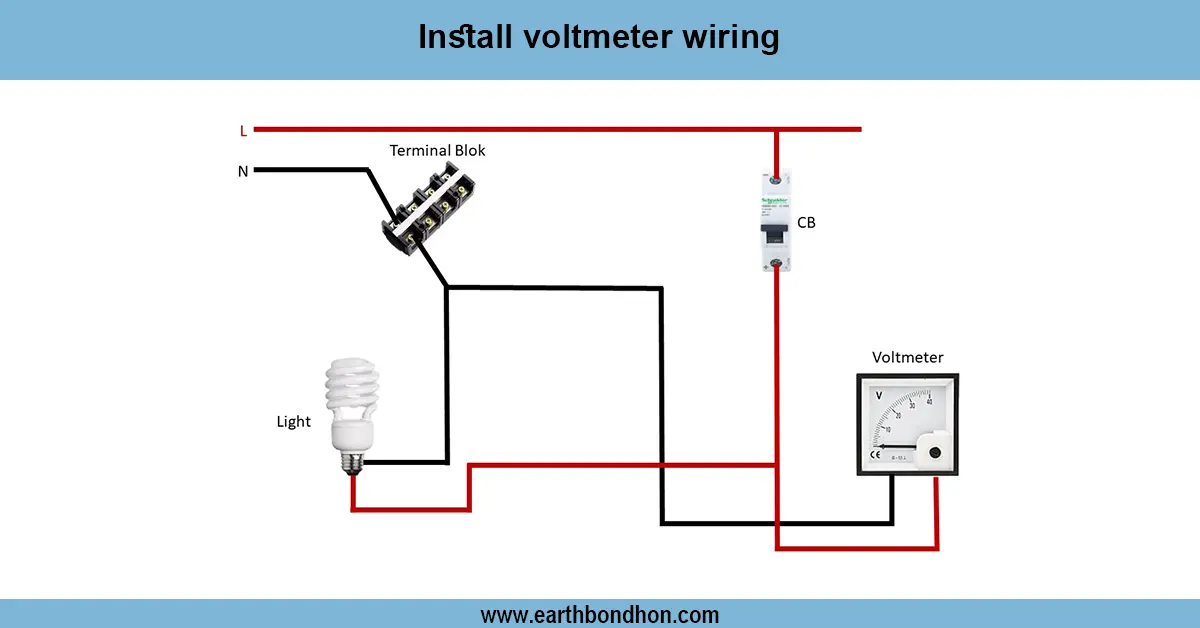
Testing is a requirement after the ATS automatic transfer switch has been installed. An initial step is checking all connections of the main supply, generator, and output to the distribution board. Fit the voltmeter and check both sides with respect to the correct input voltage. Part 1. Test with the utility supply in normal conditions. Next, pretend you have lost power due to the disconnection of the main line. The ATS must power up the generator and assign the load. Check the switching time, ammeter, and voltmeter to ensure a steady output. After recovery of the main supply, make the ATS change back to its normal position and turn off the generator. Check all protective units, such as RCCB, MCB, and relays, to ensure they are working. Mark the ATS panel so that it can be easily identified. Last-minute changes ensure stable operation, safety, an,d without operator intervention, a constant power supply.