street light control with timer wiring diagram
Learn street light control wiring with a timer for automatic ON/OFF, energy saving, and secure operation of public lighting systems.

street light control timer wiring
Street lights timer enabled control enables automatic switching of ON and OFF of the lights with a timer relay or programmable digital timer system that saves energy and the street lights boost the safety of the people with limited manual intervention.
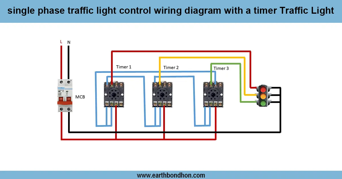
timer controlled street light wiring diagram:
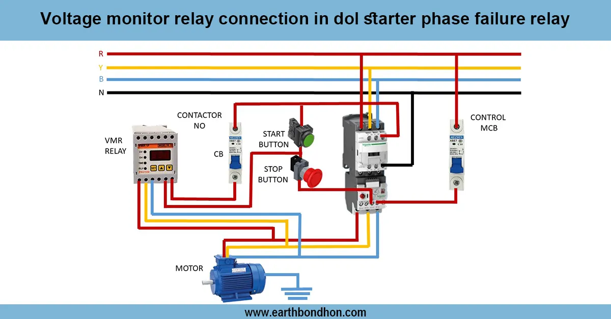
A street light controller is a time-controlled light that switches the lights on and off in the streets based on a preset time. It employs a digital timer or a timer relay, which is wired in series to the street light circuit and which turns on a contactor or a relay. The timer may be set to switch lights ON when it gets dark and OFF when it gets bright or according to set timetables, which will make it energy efficient and less manual. Ordinarily, the wiring scheme has a main power supply, MCB / fuse, timer, contactor, and street lights, and the earthing is appropriately earthed to ensure safety. The contactor separates the high-power load of the street lights and the low-power load of the timer. After the wiring diagram, the automatic control will be reliable, which will extend the life of the lamp and avoid accidental short circuiting or overloading. Public safety and energy saving. Street light automation on Light Timers in urban, residential, and industrial environments is commonly used to save energy and enhance public safety.
Work & Installation (Input → Output,)
- Input Supply: Connect 230/240V AC single-phase supply to MCB/fuse.
- Timer Connection: Wire the timer in series with the contactor coil.
- Contactor/Relay: Use a contactor to switch the high-power street light load safely.
- Street Lights: Connect lights to the contactor output terminals.
- Programming Timer: Set ON/OFF schedule according to dusk/dawn or fixed times.
- Earthing: Ensure proper grounding for timer, contactor, and lights.
- Manual Override: Optional switch for manual control.
- Operation: Timer energizes contactor coil, closing main circuit to lights; de-energizes to switch OFF.
- Output: Lights turn ON/OFF automatically at scheduled times, saving energy and enhancing safety.
Testing & Final Adjustments
Once the wires have been wired together, switch on the main supply and test the timer settings. Check to see that the contactor energises at the adjustable ON time, and the street lights go on. Check the OFF time to make sure that the lights go off when the program is scheduled. Check all the wiring connections, insulation, and earthing. Manual override of the test to ensure that it works in an emergency (test manual override may be present). Set timer options depending on season or daylight. Alarm on abnormal noises of the contactor or flickering lights. Make sure that all MCBs, fuses, as well as overload protection gadgets are matched appropriately. Label everything as a way of easy maintenance. Effective testing guarantees effective automatic functioning, eliminates energy wastage, and increases the service life of street lamps and other related equipment. Maintenance is done regularly, such as cleaning timer contacts, inspecting relays, and ensuring dearthing integrity.
Frequently Asked Questions - street light control with timer wiring diagram:
What is street light timer control?
A system to automatically switch street lights ON and OFF using a timer.
Which timer is used?
Either electromechanical or digital programmable timer.
Is a contactor required?
Yes, to safely switch high-power street light loads.
Can I manually control lights?
Yes, optional manual override switch can be installed.
What supply voltage is used?
Single-phase AC, typically 230/240V.
Is earthing necessary?
Yes, for safety of lights, timer, and contactor.
Can the timer be programmed for seasonal changes?
Yes, schedules can be adjusted for daylight variations.
Does it save electricity?
Yes, lights operate only during required periods.
What protection devices are needed?
MCB, fuses, or overload protection according to load rating.
Why follow the wiring diagram?
Ensures safe, reliable, and energy-efficient operation.