Earth Leakage Relay Wiring
Learn earth leakage relay wiring and connection diagrams to detect leakage currents, prevent shocks, and ensure safe operation of electrical systems.

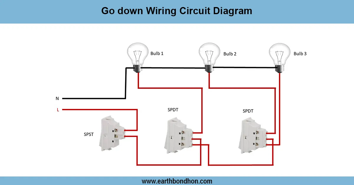
leakage protection relay diagram
ELR wiring is needed to identify leakage currents and to eliminate electrical hazards. Once the leakage is above the predetermined limit, the relay will jump and cut the supply, which will protect equipment and personnel.
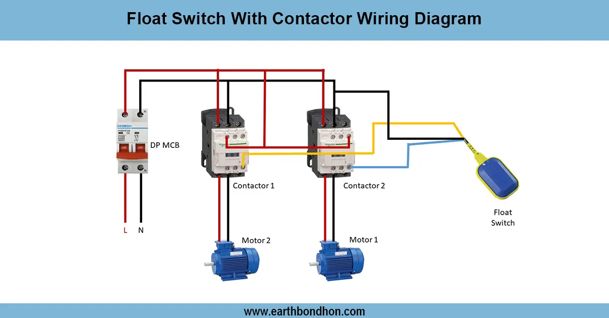
ELR connection for electrical safety
The Earth Leakage Relay (ELR) wiring and connection help to safeguard against leakage currents and avoid the danger of electric shock or fire. The ELR checks the discrepancy in line and neutral current, a nd in case there is leakage of current to earth, it cuts the circuit instantly. Correct wiring includes a line and neutral connection via the relay, an earth connection, and a downstream load. The ELR is typically used in combination with a contactor to automatically disconnect the supply in an industrial application. It is popular in electrical installations in industry, commerce, and residential structures to guard equipment and personnel. During testing, leakage currents are simulated to ensure that everything is working. Proper installation is required to achieve better safety, good detection of earth faults, and adherence to the electrical standards.
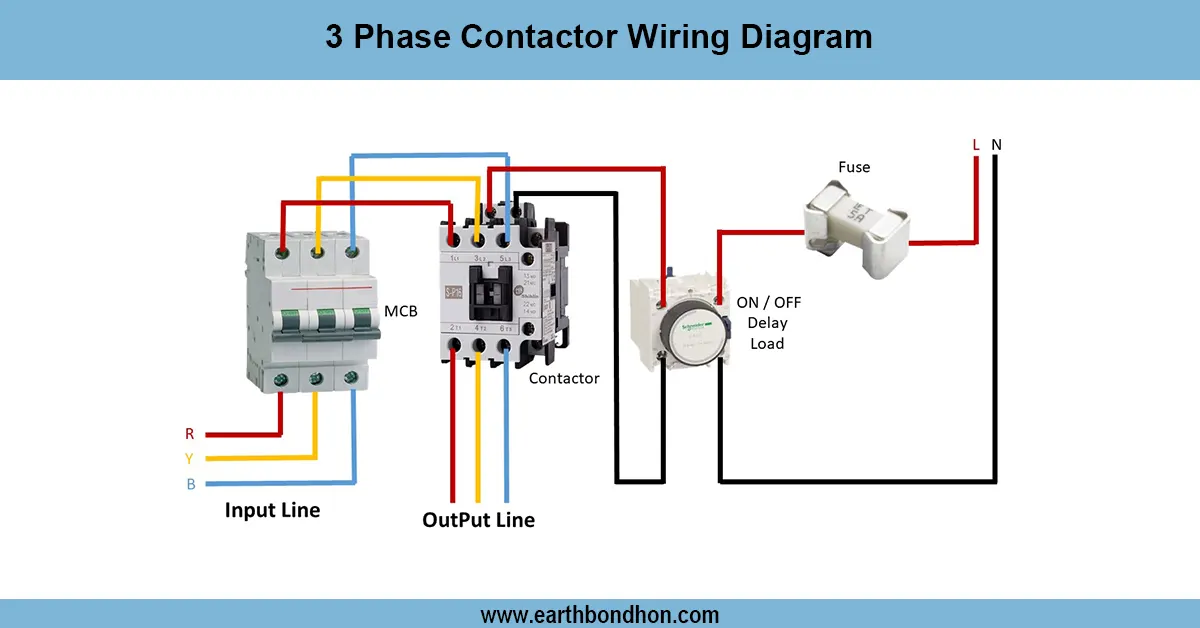
Work & Installation (Input → Output Summary)
- Incoming Supply (Line and Neutral) passes through the earth leakage relay.
- Downstream Load is connected through relay contacts.
- Earth Connection ensures leakage current flows safely to ground.
- Relay Detection measures current imbalance; if leakage exceeds threshold, relay trips.
- Contactor (optional) disconnects supply automatically for high-power loads.
- Proper wiring ensuresleakage detection, overload protection, and electrical safety.
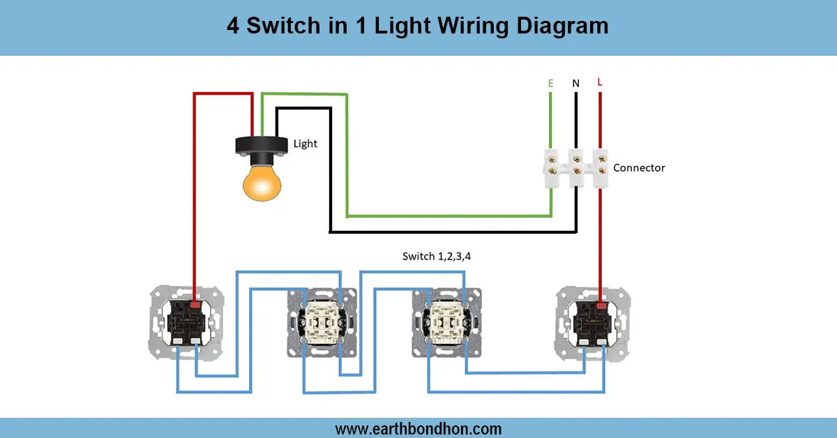
Testing & Final Adjustments
- Verify correct line, neutral, and earth connections.
- Connect supply and check ELR indicators for power ON status.
- Simulate leakage by pressing the test button; the relay should trip immediately.
- Inspect contacts, terminals, and wires for secure and insulated installation.
- Test repeated tripping for reliability.
- Check the downstream load operation after resetting the relay.
- Ensure relay rating matches supply voltage and load current.
- Verify earth continuity for proper operation.
- Confirm no unwanted tripping under normal load conditions.
- Record test results for maintenance documentation.