Automatic changeover switch wiring diagram
Learn changeover switch connection in two-way switch wiring with diagram, safe installation, and step-by-step guide for home and industrial applications.

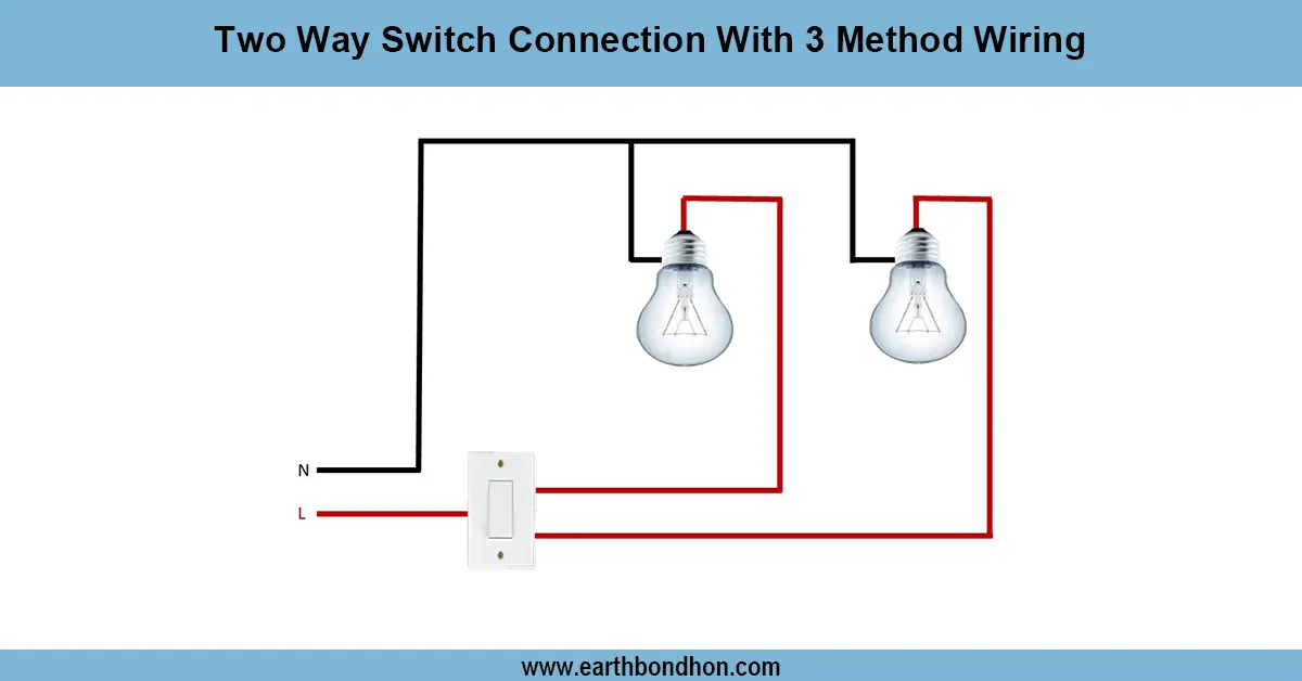
two way switch wiring with changeover
Two-way switch wiring may be achieved by a changeover switch connection that moves the load between two power sources, e.g. main supply and the generator, whilst controlling the switching between two locations. This installation provides the ability to use a two-way switching circuit that is reliable and safe in use, along with the manual changeover switch. It is also used in residential, commercial, and industrial systems, where there is a need for a reserve supply. The electrical work consists of linking the changeover switch to two supplies and passing the output over a two-way switch to control the load. Such a design will provide 24-hour and convenient power control.
Changeover connection in house wiring
A changeover switch connection, where two-way switch wiring is employed, is a convenient arrangement that fulfills two important functions: safe transfer of power sources and dual control of loads. The changeover switch enables users to alternate the load to be served by two sources of power, which include the main power supply and, because of outages, a backup generator or inverter that will provide power at all times. Upon connection of the load by the changeover switch, it is then wired to a two-way switch circuit, permitting the same load (say, lights or fans) to be controlled at two locations.
This type of wiring is mainly applied in residential, office, and lower industrial installations where continuous power and convenience are required. To ensure safety, proper wiring necessitates proper connection of the phase, neutral, and earth, and includes protective equipment like MCBs and fuses. With a changeover switch and two-way wiring, users have the advantage of both the flexibility of using backup power as well as the convenience of operating the loads. This arrangement guarantees reliability, security, and convenience in daily electricity systems.
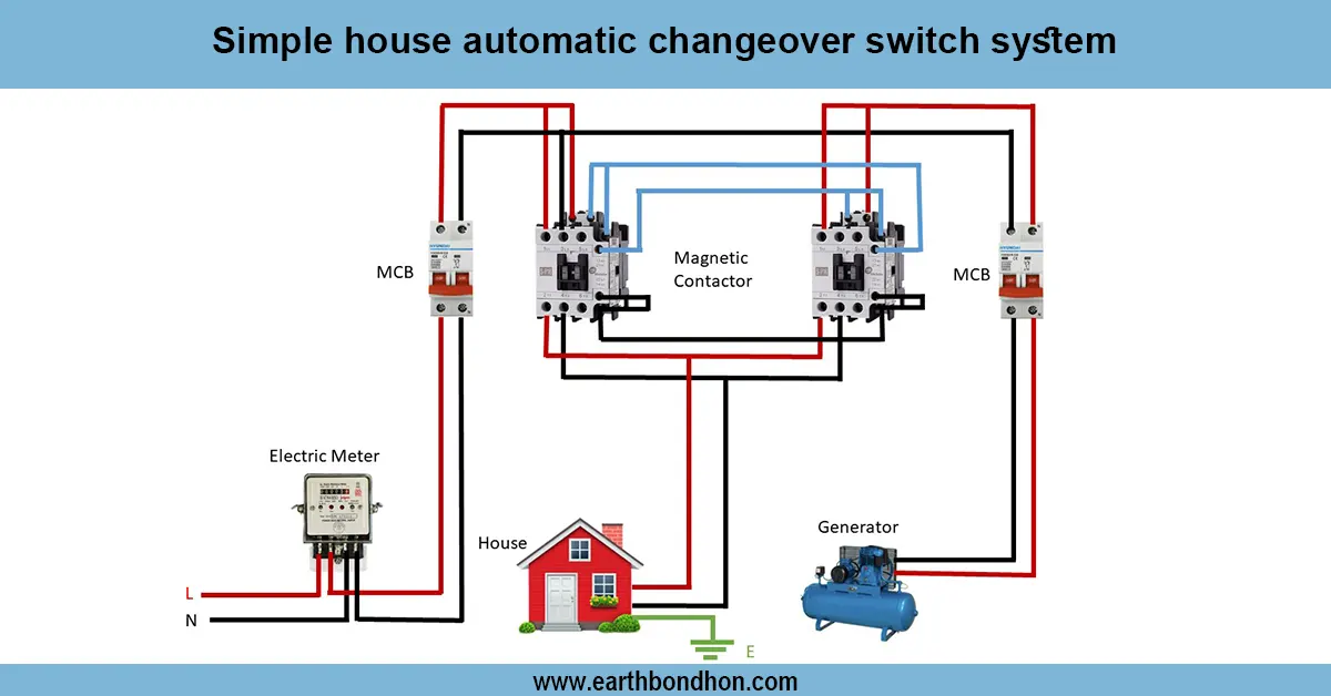
Work / Installation (Inputs → Outputs)
In this arrangement, the changeover switch is initially wired to both power supplies, which usually include the main utility supply and a backup generator or inverter. The switch provides the safe transfer of the load between the two supplies. The changeover switch output then goes to a two-way switch circuit, where the same load (lights or fans) can be controlled by controlling the changeover switch from two locations. The wiring should be correct and provide phase, neutral, and earth connections, which prevent short circuits. Overload safety should be provided by the installation of protective equipment such as MCBs and fuses. The system is easy to use since there is proper labeling on the changeover switch and two-way switch points. This integrates a wiring system with backup power switchover and adjustable load.
Testing & Final Adjustments
Once the wiring is done, the system should be tested. Check the changeover switch: 1) Select the main supply and check that the load functions correctly using the two-way switches. Then alternate the backup power supply (generator/inverter) and ensure that the same load is tested. Check to see that the two-way switches are working the load properly both ways. Measure the continuity of voltages with a multimeter and verify that it is wired with the correct phase-to-neutral. Be sure earthing is connected. Check the wiring points and tighten terminals in case there is flickering or a loose connection. Lastly, identify the changeover switch (Main / Backup) and the way switches ( Switch 1 / Switch 2). Safe, reliable, and convenient operation is promoted by propelling, and users are assured in using dual-point control of various power sources.