High Quality Rechargeable Emergency Light Circuit
Build a high-quality rechargeable emergency light circuit. Step-by-step DIY guide with components, working principle, and applications for home or office.

Home emergency light project
It is required to have a rechargeable emergency light circuit of high quality that gives continuous lighting in the event of a power failure. This DIY circuit would charge a rechargeable battery automatically and turn on LEDs in failure of a mains power failure. It is power-saving, durable, and suitable for homes, offices, and workshops.
High-quality LED emergency light circuit
The emergency light incorporates an LED-powered rechargeable battery, which is usually 12V or 6V. They are automatic charging and switching circuits that make sure that the battery will always be fully charged, and lights will automatically turn on when there is a power cut. With this circuit, electronics enthusiasts can design an effective and affordable emergency lighting system and also gain some useful philosophy of circuit design.
Key Features and Advantages
- Automatic switching from mains to battery
- Energy-efficient LED illumination
- Long-lasting rechargeable battery
- Overcharge and short-circuit protection
- Compact and easy-to-assemble design
Components Required for Emergency Light Circuit
- Rechargeable battery (12V/7Ah or suitable)
- LEDs or high-brightness LED strips
- Diode (e.g., 1N4007 for protection)
- Resistors for current limiting
- Transistor or MOSFET for switching (e.g., BC547)
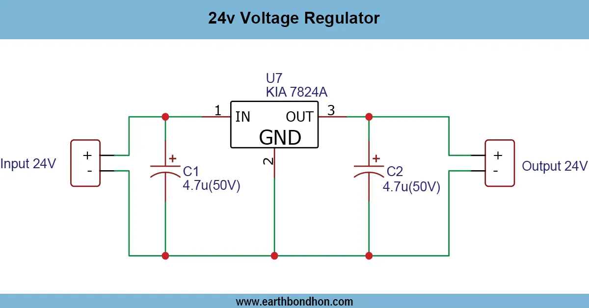
- Voltage regulator IC (optional)
- Battery charging IC or charging circuit
- Switches and connectors
- PCB or breadboard
- Wires, heat shrink, soldering tools
Working Principle
Battery Charging Circuit
When mains power is available, the charging circuit keeps the battery fully charged. The charging current is regulated to prevent battery overcharging or damage.
Automatic Light Control
A transistor or MOSFET senses the presence of mains power. When mains supply fails, it switches on the LED lights automatically.
LED Driver Section
Current-limiting resistors or voltage regulators ensure proper LED brightness and prevent damage due to excess current.
Overcharge and Short-Circuit Protection
A diode prevents reverse current flow from the battery. Fuses or current limiters protect against short circuits.
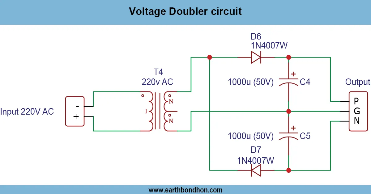
Circuit Diagram of High-Quality Emergency Light
- Connect the rechargeable battery to the charging circuit.
- Add a diode in series to prevent reverse current.
- Integrate a transistor or MOSFET for auto-switching.
- Connect LEDs with appropriate resistors or a regulator.
- Add an optional fuse for protection.
- Test operation with mains ON and OFF.
Step-by-Step Construction Guide
- Assemble the battery charging circuit on PCB.
- Connect the battery and test charging voltage.
- Wire LED section with resistors.
- Install transistor/MOSFET for auto-switching.
- Mount components safely on a board or enclosed box.
- Test charging and emergency lighting functions.
- Adjust brightness using resistors or regulator.
Applications of Rechargeable Emergency Light
- Home lighting during power outages
- Office emergency illumination
- Workshops or industrial areas
- Portable emergency lamps
- DIY learning projects
Safety Precautions
- Avoid overcharging battery
- Use insulated wires and secure terminals
- Do not short battery terminals
- Use heatsinks if transistor/MOSFET heats up
- Test before final installation
Troubleshooting Common Issues
LEDs Not Lighting
- Check battery voltage and wiring
- Verify transistor/MOSFET switching
Battery Not Charging
- Check diode orientation
- Ensure correct mains voltage
Overheating or Flickering
- Check current-limiting resistors
- Verify LED connections and transistor rating