

Music Reactive LED
Create a music-reactive LED circuit that lights up LEDs based on audio signals. Ideal for visual sound effects, party lights, and hobby electronics projects.

music reactive LED circuit
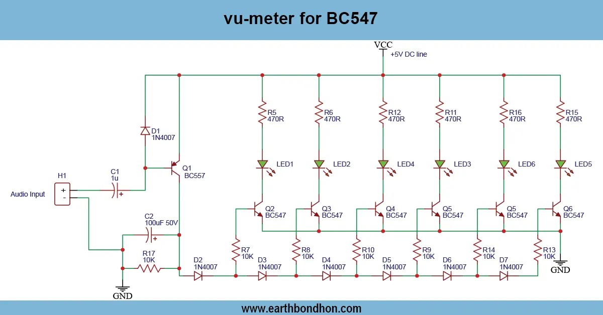
A music-reactive LED circuit is an LED circuit that reacts to audio signals; the lights are lit according to the volume of sound. It gives a graphical visualization of music and can be used in DIY projects of music and hobby.
transistor LED music circuit
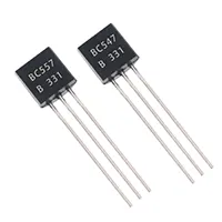
A music-reactive LED Circuit is used to illuminate LEDs as the audio signal changes, and it produces visual effects. The components used in this project are basic and include transistors (BC547 or BC557), resistors, capacitors, and LEDs. The signal of an audio source, such as a mobile, MP33 player, or microphone, is introduced into the circuit and is amplified and filtered to produce a current to power the LEDs. The various LEDs will be lit in a sequence depending on the intensity of the sound, providing a visual effect to the sound. You may join up to several LEDs in series, parallel or in the form of bars to form complex displays. The circuit is ideal to hobbyists, students, and DIY enthusiasts who would like to integrate electronics and music, which may be used in small parties, on the desk, or on a demonstration. Correct choice of resistors and power supply value will guarantee safe operation and bright light of LED.
Work / Installation (Inputs → Outputs)
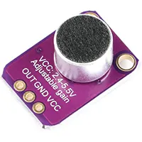
- Audio Input → From microphone, mobile, or MP3 player.
- Amplifier Stage → Boosts the audio signal using transistor or op-amp.
- Signal Filtering → Capacitors and resistors shape the signal for LED response.
- LED Driver → Transistor switches LEDs according to audio amplitude.
- Output → LEDs light up dynamically with music beats.
- Installation → Assemble components on breadboard or PCB, connect audio input, ensure proper LED polarity, power the circuit, and test responsiveness.
Testing & Final Adjustments
Connect the power and the audio after assembling the circuit. Monitor LED reaction; they are expected to illuminate with the beat and the amount of music Volume. The value of the resistors can be altered to adjust the sensitivity and brightness of LEDs. Always connect the LEDs with the right polarity to prevent destruction. Use various audio tracks to ensure a dynamic response. Adjust the values of capacitors and resistors to fine-tune to give smooth effects. Protective elements on a PCB or enclosure. Safe operation, stable performance of LEDs, and an interactive display that can be used to react to music are guaranteed with proper testing and are appropriate for small parties or experiments.