3 phase meter connection diagram:
This diagram shows how to make 3 phase meter connection diagram. In this circuit, we use a three-phase energy meter, an FP MCB ( Four Pole Miniature Circuit Breaker ), a neutral wire connector, and an earth wire connector. This circuit is very simple and easy to make. If you want to know more about this circuit please check our youtube video below the post.
Advertisements
Diagram of 3 phase meter connection diagram:

Components needed For this Project:
You can get the components from any of the sites below:
- Three Phase Energy Meter [See Buy Click Amazon]
- TP MCB 32A [See Buy Click Amazon]
- Busbar wire [See Buy Click Amazon]
*Please note: These are affiliate links. I may make a commission if you buy the components through these links. I would appreciate your support in this way!
Advertisements
Components used to make the 3 phase meter connection diagram:
01. 3 Phase Energy Meter:
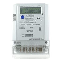
The Meter Which is used for Measuring the Power of the 3-phase supply is known as the 3-phase energy meter. A 3-phase Energy meter is a 3-phase 4-wire direct Connected meter that is Used to estimate the electricity on the Three-phase power supply, mostly for residential & commercial use. A 3-phase meter helps consumers & utilities in revenue protection. The 3-phase meter is Constructed by Connecting the 2 single-phase meters through the shaft.
02. TP MCB:
The full meaning of MCB is Miniature Circuit Breaker for TP MCB. MCB is an electromagnetic switch or device. If for any reason a short circuit occurs in the supply line or load line (line to line or line to neutral) or in case of overload MCB. the MCB automatically trips and disconnects the main line circuit or household power supply Connection. TP MCB In 3 Pole MCB, Switching & Protection is affected in only 3-Phases and the Neutral is not part of the MCB. 3 pole MCB signifies the Connection of Three Wires for a 3-Phase system Red-Yellow-Blue Phase. 3-Phase Supply Only Without Neutral.

03. Busbar:
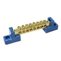
A busbar is a type of Electrical conductor. It is made of copper brass or aluminum. Busbar is most commonly used in factories. We supply the power from the transformer to the busbar. We take the electricity from this busbar to the circuit breaker. The advantage of using a busbar is that through it we can provide multiple power connections in multiple places very easily. How many thick copper bars are aggregates of busbars? A copper bar is rectangular (rectangular) copper type or triangular in shape.
Thank You for visiting the website. Keep visiting for more Updates.
Read more Single Phase Wiring
What is a kilowatt-hour (kWh) | kwh formula | What does kwh mean
Introduction to Electrical Units and CircuitskW and kWh on your electricity bill As your home uses electricity during...
What is the Difference Between kVA | What does KVA mean | kVA formula
Difference Between KVA ExplainedWhat does KVA Mean? There are technical terms aplenty when it comes to generators, and...
Power Factor | Power Unit | Energy | Electricity Unit
Power factor definition | Calculating Power FactorPower Factor Values In a purely resistive circuit, the power factor...
0 Comments