8-Pin Timer Relay Wiring:
This Diagram shows how to make 8 Pin Timer Relay Wiring. In this circuit Diagram, we use an 8-Pin Timer Relay, and 2 room lights, 3 SP MCBs ( Single Pole Miniature Circuit Breaker ). First, we input phase and neutral power to SP MCBs, then from SP MCB to input power light bulb and timer relay like our diagram. If you need clear details about our circuit diagram please check our youtube video.
Advertisements
Diagram of 8-Pin Timer Relay Wiring:

Components needed For this Project:
You can get the components from any of the sites below:
- SP MCB 10A [See Buy Click Amazon]
- 8 Pin Timer 220V AC [See Buy Click Amazon]
- CFL Light [See Buy Click Amazon]
*Please note: These are affiliate links. I may make a commission if you buy the components through these links. I would appreciate your support in this way!
Advertisements
Components used to make the 8-Pin Timer Relay Wiring:
01. SP MCB:

In single-pole MCB, Switching and protection are Affected in only one Phase. Single phase supply to break the phase only. A single Pole breaker is Typically used with 120-volt Circuits, and a 6-20 amps Miniature Circuit Breaker. They are constructed with one Line Wire and one Neutral wire. A Single Pole switch is the most basic General-Purpose switch that you use to Control a light or another device from one location. These Switches have 2 Brass-Colored screw Terminals Connected to the hot Power source wires. Pole refers to the number of Circuits Controlled by the Switch SP Switches Control only one Switch Electrical Circuit.
02. 8-Pin Timer Relay:
A timer is a type of time-switching device that controls and controls Electrical circuits and electrical and electronic devices through time setting (on/off). The timer is basically 8-pin. Like other controlling devices the timer has a coil and when this coil is magnetized, the timer works on/off. The timer has 2 common ends and each common end has normally close and normally open options. When the timer is set by time, the timer trips at the end of that time and turns the common is normally closed (on) to open (off) and normally open (off) to close (on). This is how the timer works.
03. Light:

CFL stands for Compact Fluorescent Lamp which is an improved version of tube lights of earlier days. Like tube lights, it is a vacuum glass tube with fluorescent powder coating which is not as long and straight as tube lights but curved/twisted compact, or small in size. Like a tube light, it has electrodes or filaments at both ends. But in this case, instead of a choke, there is an electronic circuit that drives the Compact Fluorescent Lamp. Because the red wave is less in the light of the Tubelight and Compact Fluorescent Lamp, the object looks a little pale or the correct color of the object does not appear.
Thank You for visiting the website. Keep visiting for more Updates.
Frequently asked questions
A timer relay is a combination of an electromechanical output relay and a control circuit the contacts will open or close before or after a preselected time.
8 pin relays have 2 normally open circuit diagrams and 2 normally closed circuits, as opposed to 1 of each. From left to right at the power supply top of a relay, the pins are numbered 6,5,4 and 3. From left to right at the bottom of a relay, the power supply pins are numbered 7,8,1 and 2.
Upon application of input voltage, the Circuit Diagram time delay relay is ready to accept a trigger. When the power supply trigger is applied, the time delay (t1) begins. At the end of the time delay (t1), the power supply output is energized. When the power supply trigger is removed, the power supply output contacts the remainder and is energized for the time delay (t2).
Using an 8-channel relay means that the relay module has 8 individual relays, each capable of controlling a separate circuit. This allows for the centralized control of multiple devices or circuits using a single control signal.
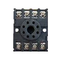
The 8-pin IC Socket base adaptor is an 8-pin IC holder, the power supply which can be soldered directly onto the PCB. The IC can be removed from this socket when the power supply is required. The IC is placed on the socket at the power supply time of use. This base acts as a removable IC holder.
Read more Single Phase Wiring
What is a kilowatt-hour (kWh) | kwh formula | What does kwh mean
Introduction to Electrical Units and CircuitskW and kWh on your electricity bill As your home uses electricity during...
What is the Difference Between kVA | What does KVA mean | kVA formula
Difference Between KVA ExplainedWhat does KVA Mean? There are technical terms aplenty when it comes to generators, and...
Power Factor | Power Unit | Energy | Electricity Unit
Power factor definition | Calculating Power FactorPower Factor Values In a purely resistive circuit, the power factor...
0 Comments
Trackbacks/Pingbacks