Any single color large LED matrix display which is formed from a couple of large 8×8 LED matrix modules daisy-chained together. These 8×8 LED matrix modules are around 144mm x 144mm in size.

Using a 7219 you’ll drive 64 LEDs while you simply need 3 wires to interface it to a microcontroller. additionallyyou’ll daisy chain multiple 7219 chips for bigger displays. There are 16 output lines from the 7219 driving 64 individual LEDs. This sounds impossible but the driving method makes use of the way our eyes work. Persistence of vision is exploited to form the LEDs appear to get on all the time when actually they’re not. In fact, the LEDs are arranged as an 8×8 set of rows and columns. Each column is pulsed for a brief time while the row bits for that column are driven.

Our eyes remember a flash of sunshine for about 20ms, so once you continuously flashlight (or an LED) at a rate at or faster than 20ms, then it appears that the sunshine never popsthis is often how the 7219 works. All the LEDs are individually turned on for a brief time, at a rate greater than 20ms.

The matrix that we’re getting to use during this guide is an 8×8 matrix which suggests that it’s 8 columns and eight rows, so it contains a complete of 64 LEDs.

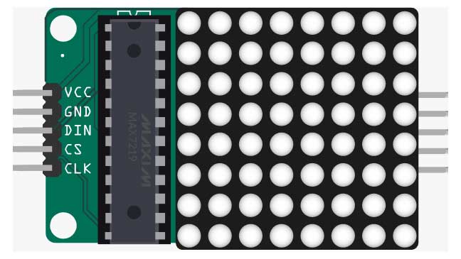
Pinout of 8×8 Matrix Display

You only need to connect 5 pins from the dot matrix to your Arduino board. The wiring is pretty straightforward:

Dot-matrix pin Wiring to Arduino Uno
GND GND
VCC 5V
DIN Digital pin
CS Digital pin
CLK Digital pin

SPECIFICATIONS:

01.  Parameter MAX7219

02. Power Supply = 4.0V ~ 5.5V

03. Supply Current = 330mA

04. Segment drive source current = 40mA

05. Scan rate = 500-1300Hz (800Hz Typ.)

06. CLK max = 10MHz

07. Voltage  +5V.

08. Vih (input high) min 3.5V

New Post