Introduction to Arduino Mega
It is a microcontroller board supported Atmega 2560 microcontroller. Arduino Boards have revitalized the automation industry with their easy to use platform where everyone with little or no technical background can start with learning some basic skills to program and run the board.
I have updated articles previously on Arduino Uno, Arduino Nano, an Arduino Pro Mini. of these boards function similarly in a method or the opposite. There are some basic features like PCB layout design, size, number of analog pins and breadboard-friendly nature that make them different from one another. In terms of coding, these boards are programmed in Arduino IDE software and you don’t get to attach extra components or devices to place them within the running condition. Everything is already built on the board that creates this device readily available. Just plug and play with the board as per your requirement.
All the boards mentioned above work perfectly for a variety of Arduino Projects once you require an easy task to be completed with fewer I/O pins and memory. However, when the character of the project goes complex, a board with less memory fails to finish the task. this is often where Arduino Mega 2560 comes handy. This board comes with 54 pins and 16 analog pins with more memory to store the code. Sounds crazy, isn’t it? because of technology that keeps you covered in every aspect and provides support in any way when it involves fulfilling your technical needs.
Information Of Mega
- Arduino Mega 2560 may be a Microcontroller board supported Atmega2560. It comes with more memory space and Input/Output pins as compared to other boards available within the market.
- There are 54 digital I/O pins and 16 analog pins incorporated on the board that make this device unique and stand out from others.
- Out of 54 digital Input/Output, 15 are used for PWM (pulse width modulation).
- A quartz oscillator of 16MHz frequency is added on the board.
- This board comes with a USB cable port that’s wont to connect and transfer code from the pc to the board.
- DC power jack is including the board that’s wont to power the board. Some versions of the Arduino board lacks this feature like Arduino Pro Mini doesn’t accompany DC power jack.
- ICSP header may be a remarkable addition to Arduino Mega which is employed for programming the Arduino and uploading the code from the pc.
- This board comes with two transformers i.e. 5V and 3.3V which provides the pliability to manage the voltage as per requirements as compared to Arduino Pro Mini which comes with just one transformer.
- There is no much difference between Arduino Uno and Arduino Mega except later comes with more memory space, bigger size and more I/O pins.
- Arduino software called Arduino IDE is employed to program the board which may be a common software used for all boards belonged to the Arduino family.
- The availability of Atmega16 on the board makes it different than Arduino Pro Mini which uses USB to serial converter to program the board.
- There are a push-button and 4 hardware interface called USART which produces a maximum speed for fixing communication.
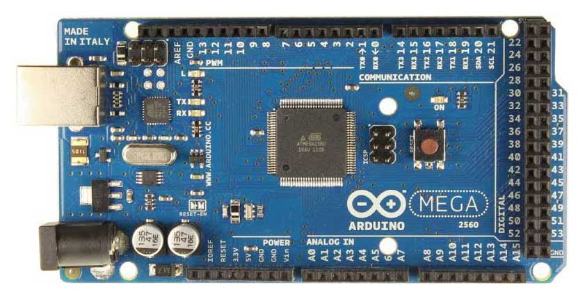
Pinout of Arduino Mega
Arduino Mega Pinout

- 5V & 3.3V: This pin is used to provide output regulated voltage around 5V. This regulated power supply powers up the controller and other components on the board. It can be obtained from Vin of the board or USB cable or another regulated 5V voltage supply. While another voltage regulation is provided by 3.3V pin. The maximum power it can draw is 50mA.
- GND: There are 5 ground pins available on the board which makes it useful when more than one ground pins are required for the project.
- Vin: It is the input voltage supplied to the board which ranges from 7V to 20V. The voltage provided by the power jack can be accessed through this pin. However, the output voltage through this pin to the board will be automatically set up to 5V.
- Serial Communication: RDX and TXD are the serial pins used to transmit and receive serial data i.e. Rx represents the transmission of data while Tx used to receive data. There are four combinations of these serial pins are used where Serail 0 contains RX(0) and TX(1), Serial 1 contains TX(18) and RX(19), Serial 2 contains TX(16) and RX(17), and Serial 3 contains TX(14) and RX(15).
- Reset: This pin is used to reset the board. Setting this pin to LOW will reset the board.
- External Interrupts: Six pins are used for creating external interrupts i.e interrupt 0(0), interrupt 1(3), interrupt 2(21), interrupt 3(20), interrupt 4(19), interrupt 5(18). These pins produce interrupts by a number of ways i.e. providing LOW value, rising or falling edge or changing value to the interrupt pins.
- SPI: Communication. SPI stands for Serial Peripheral Interface used for the transmission of data between the controller and other peripherals components. Four pins i.e. 50 (MISO), 51 (MOSI), 52 (SCK), 53 (SS) are used for SPI communication.
- LED: This board comes with a built-in LED connected to digital pin 13. HIGH value at this pin will turn the LED on and LOW value will turn it off. This gives you the change to nursing your programming skills in real-time. AREF. AREF stands for Analog Reference Voltage which is a reference voltage for analog inputs.
- Analog Pins: There are 16 analog pins incorporated on the board labeled as A0 to A15. It is important to note that all these analog pins can be used as digital I/O pins. Each analog pin comes with a 10-bit resolution. These pins can measure from ground to 5V. However, the upper value can be changed using AREF and analogReference() function.
- I2C: Two pins 20 and 21 support I2C communication where 20 represents SDA (Serial Data Line mainly used for holding the data) and 21 represents SCL(Serial Clock Line mainly used for providing data synchronization between the devices)
Applications
- Developing 3D printer
- Controlling and handling more than one motors
- Interfacing of number of sensors
- Sensing and detecting temperature
- Water level detection projects
- Home automation and security systems
- Embedded Systems
- IoT applications
- Parallel programming and Multitasking