Introducing
The Arduino maybe a tiny pc that you simply will program to browse info from the globe around you and to send commands to the ski world. All of this can be doable as a result of you’ll connect many devices and parts to the Arduino to try and do what you wish. you’ll do wonderful comes with it, there’s no limit for what you’ll do, victimization your imagination everything is possible!
What is an Arduino?
The Arduino is the board that you can see in the picture below.
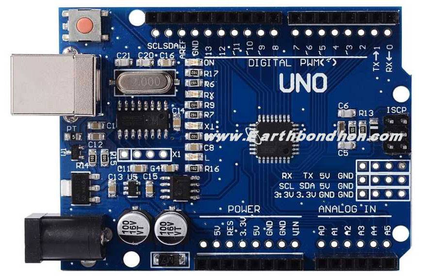
Basically, it’s a little laptop that you simply will connect with electrical circuits. This makes it straightforward to browse inputs – browse knowledge from the surface – and management outputs – send a command to the surface. The brain of this board (Arduino Uno) is associate degree ATmega328p chip wherever you’ll store your programs that may tell your Arduino what to try and do.
Exploring the Arduino Uno board
In the figure below you can see an Arduino board labeled. Let’s see what each part does.
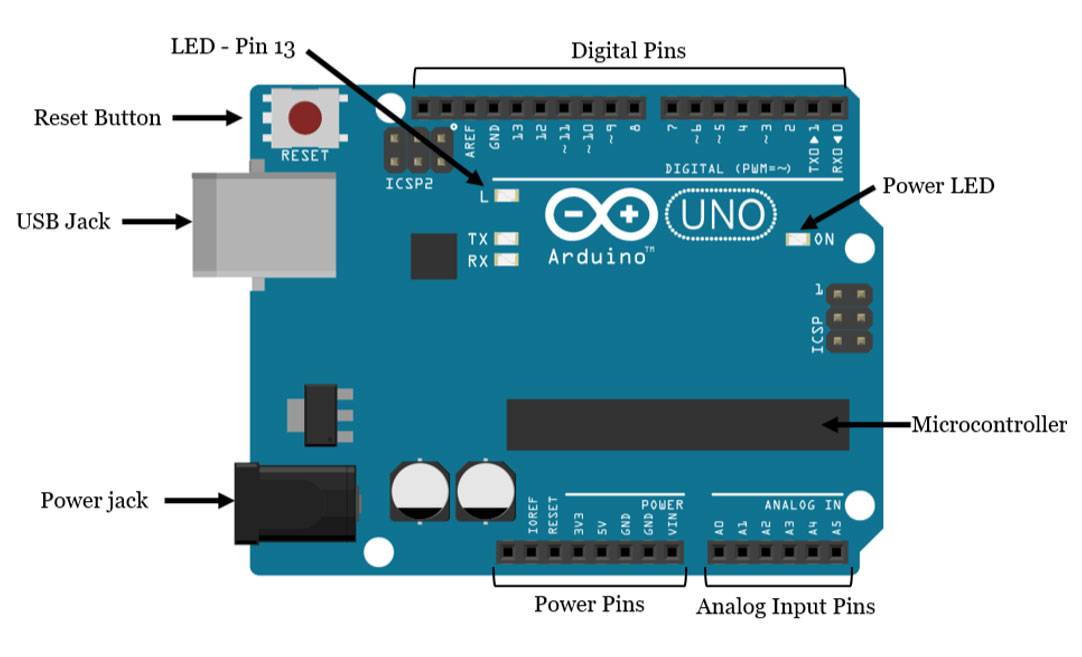
- Microcontroller: the ATmega328p is the Arduino’s brain. Everything on the Arduino board is meant to support this microcontroller.
- Digital pins: Arduino has 14 digital pins, labeled from 0 to 13 that can act as inputs or outputs. When set as inputs, these pins can read voltage. They can only read two different states HIGH or LOW. When set as outputs, these pins can apply voltage. They can only apply 5V (HIGH) or 0V (LOW).
- PWM pins: These are digital pins marked with a ~ (pins eleven, 10, 9, 6, 5 and 3). PWM stands for “pulse dimension modulation” and permits to form digital pins output “fake” variable amounts of voltage. You’ll learn additional concerning PWM later.
- TX and RX pins: digital pins zero and one. The T stands for “transmit” and also the R for “receive”. Arduino uses these pins to speak with the pc. Avoid victimization these pins, unless you’re running out of pins.
- LED attached to digital pin 13: This is useful for an easy debugging of the Arduino sketches.
- TX and RX pins: these pins blink when there is information being sent between the computer and the Arduino.
- Analog pins: the analog pins are labeled from A0 to A5 and are most frequently wont to browse analog sensors. they will browse totally different amounts of voltage between zero and 5V. in addition, they will even be used as digital output/input pins just like the digital pins.
- Power pins: The Arduino has three.3V or 5V offer, that is basically helpful since most elements need three.3V or 5V. The pins tagged as “GND” area unit the bottom pins.
- Reset button: when you press that button, the program that’s presently being run in your Arduino can begin from the start. you furthermore might have a Reset pin next to the facility pins that act because of the button. after you apply a tiny low voltage to its pin, it’ll reset the Arduino.
- Power ON LED: will be on since power is applied to the Arduino.
- USB jack: Connecting a male USB A to male USB B cable is how you upload programs from your computer to your Arduino board. This also powers your Arduino.