Basic House Wiring Diagram:
This diagram shows how to make basic house wiring. In this diagram, we use a single-phase energy meter, a DP MCB ( Double Pole Miniature Circuit Breaker ), two LED lights, a fan, four 3-pin sockets, two switches, a refrigerator, and a fan regulator. First, we need to input power to the energy meter, then from the energy meter to the input line DP MCB, then from DP MCB to input power to all switch sockets, and load ( fan, lights, refrigerator ). Now our circuit is ready for use. If you want to know more about this circuit diagram please check our youtube video below the article.
Advertisements
Diagram of Basic House Wiring:

Components needed For this Project:
You can get the components from any of the sites below:
- Single Phase Energy Meter [See Buy Click Amazon]
- DP MCB 32A [See Buy Click Amazon]
- Gang Socket [See Buy Click Amazon]
- Gang Switch [See Buy Click Amazon]
- Gang Dimmer [See Buy Click Amazon]
- Refrigerator Freezer [See Buy Click Amazon]
- CFL Light [See Buy Click Amazon]
- Ceiling Fan 56-Inch [See Buy Click Amazon]
*Please note: These are affiliate links. I may make a commission if you buy the components through these links. I would appreciate your support in this way!
Advertisements
Components used to make the Basic House Wiring:
01. Single Phase Energy Meter:

A Single-Phase Energy Meter is a sort of Watt-Hour meter. It consists of two Electromagnets. Single-Phase Energy Meter is also Popularly known as a watt-hour meter. 1 Magnet is called the shunt magnet Ml which is Mounted with a Pressure coil. The Pressure coil is a long coil Made of fine Copper wire that is connected across the Supply single-phase line. Single-phase energy meters are suitable for measuring single-phase AC current flow frequencies of 50/60 Hz, which are used for fixed indoor installation systems.
02. DP MCB:
DP MCB In 2 Pole MCB, switching & protection is affected in phases and the neutral. A Double Pole or DP Switch is a Switch that Controls 2 Circuits at the same time. In terms of Residential Switching, this Normally means it Switches the live and Neutral at the same time. In Layperson Terms, Double Pole switches or DP Switches are Exclusively Designed to Control 2 Different Electrical Circuits at the same time, which allows the Appliances to Isolate safely and reliably. Fan or light Combinations and Medical Equipment are some of the many applications for DP Electrical Switches and Electrical components.

03. 3-Pin Socket:
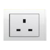
A Power Socket is a Device to Which Electrical Devices Can Be Connected to Receive the Electric Current Required For Their Operation. Connected by a System of Cables to a Power Source, Usually, an Electricity Generation Facility operated by an energy Production company, generally has no moving parts. Instead, it contains metal strips that make contact with the prongs of an Electric plug inserted into the socket. It is Through these Contacts That the Electric current is Transmitted. Electrical Devices that connect to a Power Source Through a Power Socket are Considered to be Portable Because they can easily be Connected and Disconnected From the Power Source.
04. Switch:
An SPST (Single Pole Single Throw) Switch is a Switch That only Has a Single Input and can Connect Only to one Output. This means it Only Has one Input Terminal and Only 1 Output Terminal. A Switch is a Mechanical or Controlling Device That Changes the Flow of Current Direction or Interrupts the Flow of Current Within a Circuit diagram. An electrical line using Single Pole Single Throws (SPST) is Perfect for on-off switching. When the SPST is closed, the Circuit is Closed and the light from the lamp switches on the system. When The Single Pole Single Throw (SPST) is then opened, the light from the lamp goes out and the Circuit is off.

05. Fan Regulator:
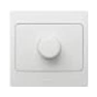
A Ceiling Fan is a fan Mounted on the Ceiling of a Room or space, Usually, Electrically Powered, That Uses hub-mounted Rotating Blades to Circulate air flow. They cool people effectively by increasing speed. It Doesn not Cool the Air Temperature — we Feel Cooler Because the Fan Moves the Air Around Us, a Process Called Evaporative Cooling. Evaporative Cooling Works like this: A cold day will feel Even Cooler if There is a Breeze Because of the wind Chill Factor.
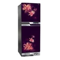
06. Refrigerator:
A Refrigerator is a Commercial and Home Appliance Consisting of a Thermally insulated Compartment and a Heat Pump that Transfers Heat from its Inside to its External Environment Refrigeration is an Essential Food Storage Technique Around the World. The lower temperature Lowers the Reproduction rate of Bacteria, so the Refrigerator reduces the rate of spoilage. A Refrigerator Maintains a Temperature a Few Degrees Above The Freezing Point of Water.
07. Light:

CFL stands for Compact Fluorescent Lamp which is an improved version of tube lights of earlier days. Like tube lights, it is a vacuum glass tube with fluorescent powder coating which is not as long and straight as tube lights but curved/twisted compact, or small in size. Like a tube light, it has electrodes or filaments at both ends. But in this case, instead of a choke, there is an electronic circuit that drives the Compact Fluorescent Lamp. Because the red wave is less in the light of the Tubelight and Compact Fluorescent Lamp, the object looks a little pale or the correct color of the object does not appear.
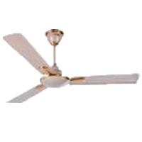
08. Ceiling Fan :
A Ceiling Fan is a fan Mounted on the Ceiling of a Room or space, Usually, Electrically Powered, That Uses hub-mounted Rotating Blades to Circulate air flow. They cool people effectively by increasing speed. It Doesn not Cool the Air Temperature — we Feel Cooler Because the Fan Moves the Air Around Us, a Process Called Evaporative Cooling. Evaporative Cooling Works like this: A cold day will feel Even Cooler if There is a Breeze Because of the wind Chill Factor.
Thank You for visiting the website. Keep visiting for more Updates.
Frequently asked questions
A house wiring diagram is a graphical power supply representation of a home's electrical system, detailing the layout and connections of wires, outlets, switches, light Circuit Diagram fixtures, and other electrical components.
A wiring Circuit diagram is a simple visual representation of the physical power supply connections and physical layout of an electrical system or circuit diagram. It shows how the electrical wires are interconnected and can also show where fixtures and components may be connected to the power supply system.
In a block diagram, the components of the system are represented as blocks and the interconnections between them are represented by lines. Block circuit diagrams are commonly used in system design, control engineering, and signal processing. On the other Currenttlou hand, an electrical schematic is a detailed circuit diagram.
An electrical symbol is a graphical Circuit Diagram representation of the electrical and electronic components. These symbols help us recognize a particular electronic device in a circuit diagram. National and international Power supply standards define electrical symbols.
Ladder Circuit diagrams (sometimes called “ladder logic”) are a type of electrical notation and symbology frequently used to illustrate how electromechanical Project system switches and relays are interconnected. The 2 vertical lines are called “rails” and attach to opposite poles of a power supply, usually 120 volts AC.
Read more Single Phase Wiring
What is a kilowatt-hour (kWh) | kwh formula | What does kwh mean
Introduction to Electrical Units and CircuitskW and kWh on your electricity bill As your home uses electricity during...
What is the Difference Between kVA | What does KVA mean | kVA formula
Difference Between KVA ExplainedWhat does KVA Mean? There are technical terms aplenty when it comes to generators, and...
Power Factor | Power Unit | Energy | Electricity Unit
Power factor definition | Calculating Power FactorPower Factor Values In a purely resistive circuit, the power factor...
0 Comments
Trackbacks/Pingbacks