Digital timer with light wiring:
This diagram shows how to make a digital timer with light wiring. In this circuit, we use an RCBO ( Residual Current Circuit Breaker ), a Digital Timer, a Switch, and a light. This circuit is very simple and easy to make. if you want to know more about this circuit please check our youtube video belwo the post. Stay with our website for more updates.
Diagram of Digital timer with light wiring:

Components needed For this Project:
You can get the components from any of the sites below:
- RCBO [See Buy Click Amazon]
- Timer [See Buy Click Amazon]
- Light [See Buy Click Amazon]
- Switch [See Buy Click Amazon]
*Please note: These are affiliate links. I may make a commission if you buy the components through these links. I would appreciate your support in this way!
Components used to make the Digital timer with light wiring:
01. RCBO:
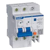
An RCBO protects electrical equipment against two types of faults; Residual current and over current. Residual current, or earth leakage as it is sometimes referred to, occurs when there is a break in the circuit which can be caused by faulty electrical wiring or if the wire is accidentally cut. When there is a break in the circuit which may be due to faulty electrical wiring or accidental cutting of the wire. To prevent the current from being redirected and causing an electric shock, the RCBO current breaker stops it.
02. Timer:
A timer is a type of time-switching device that controls and controls electrical circuits and electrical and electronic devices through time setting (on/off). The timer is basically 8-pin. Like other controlling devices the timer has a coil and when this coil is magnetized, the timer works on/off. The timer has two common ends and each common end has normally close and normally open options. When the timer is set by time, the timer trips at the end of that time and turns the common’s normally closed (on) to open (off) and normally open (off) to close (on). This is how the timer works.

03. Light:

CFL stands for Compact Fluorescent Lamp which is an improved version of tube lights of earlier days. Like tube lights, it is a vacuum glass tube with fluorescent powder coating which is not as long and straight as tube lights but curved/twisted compact, or small in size. Like a tube light, it has electrodes or filaments at both ends. But in this case, instead of a choke, there is an electronic circuit that drives the Compact Fluorescent Lamp. Because the red wave is less in the light of the Tubelight and Compact Fluorescent Lamp, the object looks a little pale or the correct color of the object does not appear.
04. Switch:
An SPST (Single Pole Single Throw) Switch is a Switch That only Has a Single Input and can Connect Only to one Output. This means it Only Has one Input Terminal and Only one Output Terminal. A Switch is a Mechanical or Controlling Device That Changes the Flow of Current Direction or Interrupts the Flow of Current Within a Circuit. Single Pole Single Throws (SPST) is Perfect for on-off switching. When the SPST is closed, the Circuit is Closed and the light from the lamp switches on. When The Single Pole Single Throw (SPST) is then opened, the light from the lamp goes out and the Circuit is off.

Thank You for visiting the website. Keep visiting for more Updates.
Read more Single Phase Wiring
3 phase motor connection diagram
3 phase motor connection diagram: This diagram shows how to make 3 phase motor connection diagram. In this circuit, we...
3 Phase Motor Starter Wiring
3 Phase Motor Starter Wiring: This diagram shows how to make 3 Phase Motor Starter Wiring. In this circuit, we use a...
Start Button and Stop Button Wiring
Start Button and Stop Button Wiring: This diagram shows how to make Start Button and Stop Button Wiring. In this...
0 Comments