Contactor Spotlights Wiring diagram:
This diagram shows how to make Contactor Spotlights Wiring diagram. In this circuit, we use RCBO, a contactor, a timer, a selector, and four spot light. This circuit is very simple and easy to make. if you want to know more about this circuit please check our youtube video belwo the post. Stay with our website for more updates.
Advertisements
Diagram of Contactor Spotlights Wiring:

Components needed For this Project:
You can get the components from any of the sites below:
- DP RCBO 20A [See Buy Click Amazon]
- Magnetic Contactor 25A [See Buy Click Amazon]
- Digital Timer 220V AC [See Buy Click Amazon]
- Selector Switch (220V AC) [See Buy Click Amazon]
- Spot Light 220V AC [See Buy Click Amazon]
*Please note: These are affiliate links. I may make a commission if you buy the components through these links. I would appreciate your support in this way!
Advertisements
Components used to make the Contactor Spotlights Wiring:
01. RCBO:
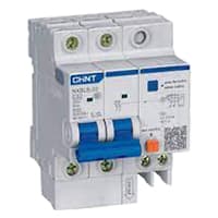
An RCBO protects Electrical equipment against 2 types of faults. Residual current and over current. Residual current. or earth leakage as it is sometimes referred to, occurs when there is a break in the circuit which can be caused by faulty electrical wiring or if the wire is accidentally cut. When there is a break in the circuit which may be due to faulty electrical wiring or accidental cutting of the wire. To prevent the current from being redirected and causing an electric shock. the RCBO current breaker stops it.
02. Magnetic Contactor:
A magnetic contactor is an electromagnetic switching device. It is generally used for controlling 3-phase Motors. The operation of a magnetic contactor is similar to that of a Relay. but a relay is used for low-power or low-voltage connections, and a magnetic contactor is used for high-power or high-voltage connections. As soon as the supply is applied to the magnetic contactor coil. its normally open contacts are closed and normally closed contacts are opened and the associated devices are also operated. This is how a magnetic contactor works.

03. Timer:

A timer is a type of time-switching device that controls and controls Electrical circuits and electrical and electronic devices through time setting (on/off). The timer is basically 8-pin. Like other controlling devices the timer has a coil and when this coil is magnetized, the timer works on/off. The timer has 2 common ends and each common end has normally close and normally open options. When the timer is set by time, the timer trips at the end of that time and turns the common is normally closed (on) to open (off) and normally open (off) to close (on). This is how the timer works.
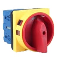
04. Selector Switch:
A Mechanical Switch That can be rotated Left, right, or center to open or close the Electrical contacts is known as a Selector switch. The Main Function of This Selector Switch is to Control Devices and also to Switch Between a Minimum of 2 or Above Electrical Circuits. The Perfect Used for Selector Switch is When Used for Controlling the Output of a Device. We know that a Selector switch is Used to control the electrical current flow in a Circuit it can also be used to both Initiate and inhibit the Current Flow.
05. Light:

CFL stands for Compact Fluorescent Lamp which is an improved version of tube lights of earlier days. Like tube lights, it is a vacuum glass tube with fluorescent powder coating which is not as long and straight as tube lights but curved/twisted compact, or small in size. Like a tube light, it has electrodes or filaments at both ends. But in this case, instead of a choke, there is an electronic circuit that drives the Compact Fluorescent Lamp. Because the red wave is less in the light of the Tubelight and Compact Fluorescent Lamp, the object looks a little pale or the correct color of the object does not appear.
Thank You for visiting the website. Keep visiting for more Updates.
Frequently asked questions
When current passes through the electromagnet, a magnetic field is produced, which attracts the moving core of the contactor. The electromagnet coil draws more current flow initially until it is inductance increases when the metal core enters the coil.
We use the contactor to turn on and off heavy, high voltage electrical devices such as motors, fans, pumps, etc. – The reason that we use a contactor is to control these heavy voltage electrical devices indirectly or safely via a PLC and not to connect the PLC directly to these outputs and devices.
The three major parts of a contactor or relay are the coil, the contacts, and the enclosure. Coil: The coil is an electromagnetic coil that, when energized, generates a magnetic field to attract the contacts and close the circuit.
The main difference between the contactor and a relay is their load capacity. Contactors are designed to handle high currents, typically above 15 amps, while relays are more suitable for low to medium current loads, usually below 15 amps.
The 3-phase, 480-volt AC power supply comes into the three normally-open contacts at the top of the contactor via screw terminals labeled “L1,” “L2,” and “L3” (The “L2” terminal is hidden behind a square-shaped “snubber” circuit diagram connected across the contactor's coil terminals).
Read more Single Phase Wiring
What is a kilowatt-hour (kWh) | kwh formula | What does kwh mean
Introduction to Electrical Units and CircuitskW and kWh on your electricity bill As your home uses electricity during...
What is the Difference Between kVA | What does KVA mean | kVA formula
Difference Between KVA ExplainedWhat does KVA Mean? There are technical terms aplenty when it comes to generators, and...
Power Factor | Power Unit | Energy | Electricity Unit
Power factor definition | Calculating Power FactorPower Factor Values In a purely resistive circuit, the power factor...
0 Comments