Automatic Transfer Switch Wiring Diagram:
This diagram shows how to make an Automatic Transfer Switch Wiring Diagram. In this circuit, we use an RCCB ( Residual Current Circuit Breaker ), a KWH meter, two DP MCBs (Double Pole Minature Circuit Breaker ), an ATS (Automatic Transformer Switch ), and a power generator. This circuit is very simple and easy to make. if you want to know more about this circuit please check our youtube video belwo the post. Stay with our website for more updates.
Advertisements
Diagram of Automatic Transfer Switch Wiring:

Components needed For this Project:
You can get the components from any of the sites below:
- DP RCCB 32A [See Buy Click Amazon]
- DP MCB 32A [See Buy Click Amazon]
- Dual Power ATS Generator Changeover [See Buy Click Amazon]
- Single Phase Generator 2000W[See Buy Click Amazon]
- Single Phase Energy Meter [See Buy Click Amazon]
*Please note: These are affiliate links. I may make a commission if you buy the components through these links. I would appreciate your support in this way!
Advertisements
Components used to make the Automatic Transfer Switch Wiring:
01. RCCB:
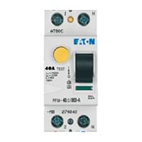
The Residual Current Circuit breaker RCCB is the Safest device to detect and Trip against Electrical Leakage current. This ensures protection against Electric shock Caused by indirect contact. Circuit breakers (CB) are automatically Operated Electrical Switches that Protect Electrical Circuits from Short-Circuiting or Overloading systems. It Protects against many major accidents. RCCB Circuit Breaker is an Electrical Wiring device whose function is to disconnect the current in the circuit.
02. DP MCB:
DP MCB In 2 Pole MCB, switching & protection is affected in phases and the neutral. A Double Pole or DP Switch is a Switch that Controls 2 Circuits at the same time. In terms of Residential Switching, this Normally means it Switches the live and Neutral at the same time. In Layperson Terms, Double Pole switches or DP Switches are Exclusively Designed to Control 2 Different Electrical Circuits at the same time, which allows the Appliances to Isolate safely and reliably. Fan or light Combinations and Medical Equipment are some of the many applications for DP Electrical Switches and Electrical components.

03. ATS:
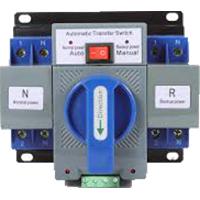
ATS is a generator & grid power line connection. ATS works to automatically start the generator when the grid power line goes down. ATS works to automatically shut down the generator when the grid power line comes again. There are 2 types of automatic transfer switches, circuit breakers, and contactors. The Circuit Breaker type has 2 Interlocked Circuit Breakers. so only one breaker can be closed at any time. The Contactor type is a Simpler Design that is Electrically Operated and Mechanically held to the system.
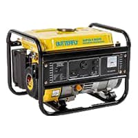
04. Power Generator:
An electric generator is a type of Electrical device that converts mechanical energy or power into electrical energy or power. However, dynamo generally refers to generators only. The first generator built was called a dynamo. This electrical device makes this conversion using the principle of kinetic electromagnetic energy generation. According to Farad is principle of electromagnetic induction, a dynamic electromagnetic induction is induced in a conductor when it passes through a magnetic flux.
05. Single Phase Energy Meter:

A Single-Phase Energy Meter is a sort of Watt-Hour meter. It consists of two Electromagnets. Single-Phase Energy Meter is also Popularly known as a watt-hour meter. 1 Magnet is called the shunt magnet Ml which is Mounted with a Pressure coil. The Pressure coil is a long coil Made of fine Copper wire that is connected across the Supply single-phase line. Single-phase energy meters are suitable for measuring single-phase AC current flow frequencies of 50/60 Hz, which are used for fixed indoor installation systems.
Thank You for visiting the website. Keep visiting for more Updates.
Read more Single Phase Wiring
What is a kilowatt-hour (kWh) | kwh formula | What does kwh mean
Introduction to Electrical Units and CircuitskW and kWh on your electricity bill As your home uses electricity during...
What is the Difference Between kVA | What does KVA mean | kVA formula
Difference Between KVA ExplainedWhat does KVA Mean? There are technical terms aplenty when it comes to generators, and...
Power Factor | Power Unit | Energy | Electricity Unit
Power factor definition | Calculating Power FactorPower Factor Values In a purely resistive circuit, the power factor...
0 Comments