11 pin relay wiring diagram:
This diagram shows how to make 11 pin relay wiring diagram. In this circuit, we use two DP MCBs ( Double Pole Minature Circuit Breaker ), and an 11 Pin Relay. First, we need to connect two DP MCBs with 11 pin relay. Now this circuit is ready for use. This circuit is very simple and easy to make. if you want to know more about this circuit please check our youtube video belwo the post. Stay with our website for more updates.
Advertisements
Diagram of 11 pin relay wiring:

Components needed For this Project:
You can get the components from any of the sites below:
*Please note: These are affiliate links. I may make a commission if you buy the components through these links. I would appreciate your support in this way!
Advertisements
Components used to make the 11 pin relay wiring diagram:
01. DP MCB:

DP MCB In 2 Pole MCB, switching & protection is affected in phases and the neutral. A Double Pole or DP Switch is a Switch that Controls 2 Circuits at the same time. In terms of Residential Switching, this Normally means it Switches the live and Neutral at the same time. In Layperson Terms, Double Pole switches or DP Switches are Exclusively Designed to Control 2 Different Electrical Circuits at the same time, which allows the Appliances to Isolate safely and reliably. Fan or light Combinations and Medical Equipment are some of the many applications for DP Electrical Switches and Electrical components.
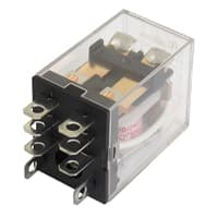
11-Pin Relay:
A timer is a type of time-switching device that controls and controls Electrical circuits and electrical and electronic devices through time setting (on/off). The timer is basically 8-pin. Like other controlling devices the timer has a coil and when this coil is magnetized, the timer works on/off. The timer has 2 common ends and each common end has normally close and normally open options. When the timer is set by time, the timer trips at the end of that time and turns the common is normally closed (on) to open (off) and normally open (off) to close (on). This is how the timer works.
Thank You for visiting the website. Keep visiting for more Updates.
Frequently asked questions
Take the leads of the multimeter and connect them across the coil terminals in a relay. For a normal coil, the multimeter should be read anywhere between the 40Ω -120Ω. If the coil is damaged i.e., it is open, the meter shows out of the range and you have to replace the relay.
All related (32) A timer circuit is an electronic component or system that is designed to control the timing of events. It can be used to turn devices on and off at specific times, measure time intervals, and trigger events after a certain amount of time has passed.
The 8 Channel Relay Module is also able to control various appliances and other types of equipment with a large current. The red working status of indicator lights is conducive to safe use. Widely used for all MCU control, industrial sector, PLC control, and smart home control.
A continuity test was a quick check to see if a circuit diagram was open or closed. Only a closed, complete circuit diagram (one that is switched ON) has continuity. During the continuity of the test, a digital multimeter sends a small current through the circuit diagram to measure resistance in the circuit diagram.
Voltage and current Parameters of the relay are in-scripted in the Case of the relay. Most relays were available in different operating voltages like 5-V, 6-V, 12-V, 24-V, etc. If the required operating voltage is supplied to the relay, the relay is very activated. The operating voltage of the relay is generally in DC.
Read more Single Phase Wiring
What is a kilowatt-hour (kWh) | kwh formula | What does kwh mean
Introduction to Electrical Units and CircuitskW and kWh on your electricity bill As your home uses electricity during...
What is the Difference Between kVA | What does KVA mean | kVA formula
Difference Between KVA ExplainedWhat does KVA Mean? There are technical terms aplenty when it comes to generators, and...
Power Factor | Power Unit | Energy | Electricity Unit
Power factor definition | Calculating Power FactorPower Factor Values In a purely resistive circuit, the power factor...
0 Comments