8 Pin Relay With Timer Wiring:
This diagram shows how to make 8 Pin Relay With Timer Wiring. In this circuit, we use two 8-pin relays, a timer, a stop switch, a start switch, two indicator lights, a DP MCB ( Double Pole Minature Circuit Breaker ), and a differential. This circuit is very simple and easy to make. if you want to know more about this circuit please check our youtube video belwo the post. Stay with our website for more updates.
Advertisements
Diagram of 8 Pin Relay With Timer Wiring:

Components needed For this Project:
You can get the components from any of the sites below:
- DP MCB 32A [See Buy Click Amazon]
- DP RCCB 16A [See Buy Click Amazon]
- 8 Pin Relay (220V AC) [See Buy Click Amazon]
- 8 Pin Timer 220V AC [See Buy Click Amazon]
- Push Button NC Switch [See Buy Click Amazon]
- Push Button NO Switch [See Buy Click Amazon]
- Indicator Light 220v AC [See Buy Click Amazon]
*Please note: These are affiliate links. I may make a commission if you buy the components through these links. I would appreciate your support in this way!
Advertisements
Components used to make the 8 Pin Relay With Timer Wiring:
01. DP MCB:

DP MCB In 2 Pole MCB, switching & protection is affected in phases and the neutral. A Double Pole or DP Switch is a Switch that Controls 2 Circuits at the same time. In terms of Residential Switching, this Normally means it Switches the live and Neutral at the same time. In Layperson Terms, Double Pole switches or DP Switches are Exclusively Designed to Control 2 Different Electrical Circuits at the same time, which allows the Appliances to Isolate safely and reliably. Fan or light Combinations and Medical Equipment are some of the many applications for DP Electrical Switches and Electrical components.
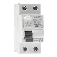
02. Differential:
The Residual Current Circuit breaker RCCB is the Safest device to detect and Trip against Electrical Leakage current. This ensures protection against Electric shock Caused by indirect contact. Circuit breakers (CB) are automatically Operated Electrical Switches that Protect Electrical Circuits from Short-Circuiting or Overloading systems. It Protects against many major accidents. RCCB Circuit Breaker is an Electrical Wiring device whose function is to disconnect the current in the circuit.
03. 8-Pin Relay:
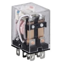
The most popular relay for automation work is the 8 Pin Relay. The 8-pin relay has a DC or AC coil as the main part. which is connected to two pins. There are two common parts. Underneath a Common part are a NO and an NC part. No part is normally open with a common part and the NC part is normally closed. The timer base used for automation is the same as the 8-relay base. That is, switching can be done using the timer base. This is basically how a relay switch works for the relay.
04. Timer:
A timer is a type of time-switching device that controls and controls Electrical circuits and electrical and electronic devices through time setting (on/off). The timer is basically 8-pin. Like other controlling devices the timer has a coil and when this coil is magnetized, the timer works on/off. The timer has 2 common ends and each common end has normally close and normally open options. When the timer is set by time, the timer trips at the end of that time and turns the common is normally closed (on) to open (off) and normally open (off) to close (on). This is how the timer works.

05. Stop Switch:

An NC (Normally Closed) Push Button is a Push Button That, In Its Default State, Makes Electrical Contact With The Circuit. An NC (Normally Closed) Push Button is a Push Button that, in its Default State, Makes electrical Contact With the Circuit. When The Button Is Pressed Down, The Switch no Longer Makes Electrical Contact And The Circuit is Now Open. When The Button is Not Pressed, Electricity Can Flow, But When it is Pressed The Circuit is Broken. This type Of Switch is Also known As a Normally Closed (NC) Switch.
06. Start Switch:
NO (Normally Open) Terms Refer to a Type of Dry Contact or Wet Contact. A Push to Make Switch Allows Electricity to flow Between its 2 contacts when held in. When the button is released, the Circuit is broken. This type of Switch is also known as A Normally Open (NO) Switching system. As its name implies, a Normally Open (NO) Switch Contact or “a Contact” is a Switch. Put very simply, a Normally Open Sensor will have no Current When in a Normal State But When it Enters an Alarm State it will have +5V applied to the Circuit.

07. Indicator Light:

An indicator lamp just Sounds Technical, Sometimes it is called a Supervisory light Indicator. Indicator lights are amber in color and can be located at the Front, the Rear, and Sometimes at the Side of the car on both the left And Right-hand sides. The Common colors used by Indicator lamps are red, yellow, blue, white, and green line system. A Panel Indicator Lamp Generally has up to 5 Differently Colored Segments to Indicate Various Conditions on the Machine or Process system.
Thank You for visiting the website. Keep visiting for more Updates.
Frequently asked questions
Upon application of the input voltage, the time delay relay was ready to accept a trigger. When the trigger was applied, the time delay (t1) begins. At the end and of the time delay (t1), the output is energized. When the triggers are removed, the output contacts remain energized of the time delay (t2).
Timing relays are commonly used in a variety of industrial and commercial applications. Some of the common applications include machines, buildings, water segments, HVAC, by other applications.
On the conventional Control Relay, the contacts are opened-closed when a voltage is applied and removed for the coil, however, for timer relays the contacts would open or close before or after an intentional period.
On- and off-delay timers the represent most typical time delay relay timers in use. Other types include interval-on-operate, flasher, or repeat cycle timers. Normally open, on-delay timers start timing when the input voltage (power) is applied.
For example, the relay may be controlled by a low-voltage, low-current supply signal that passes through a delicate switch of some sort (e.g. limit switch, proximity switch, optical sensor), and then the switching contacts of that relay may be used to control a much higher-voltage, higher-current flow circuit, and even multiple.
Read more Single Phase Wiring
What is a kilowatt-hour (kWh) | kwh formula | What does kwh mean
Introduction to Electrical Units and CircuitskW and kWh on your electricity bill As your home uses electricity during...
What is the Difference Between kVA | What does KVA mean | kVA formula
Difference Between KVA ExplainedWhat does KVA Mean? There are technical terms aplenty when it comes to generators, and...
Power Factor | Power Unit | Energy | Electricity Unit
Power factor definition | Calculating Power FactorPower Factor Values In a purely resistive circuit, the power factor...
0 Comments