


Battery Low voltage cut off Circuit
Protect your 12V battery with LM431 & TIP42C low voltage cut-off circuit. Automatically disconnects the load when the battery drops below safe voltage.

LM431 battery cut-off circuit
An automatic cut-off circuit of LM431 and TIP42C is used to automatically disconnect the battery from the load when the voltage drops below safe limits to prevent over-discharge and increase the battery life.
12V battery under-voltage cutoff
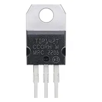
Battery Low Voltage Cut-Off Circuit with LM431 and TIP42C is a sure means of preventing deep discharge in 12V batteries. Excessive discharging of batteries may decrease the lifespan of such batteries and cause irreversible harm. The circuit takes an adjustable shunt voltage regulator (LM431) to detect the voltage of the battery. The LM431 causes the TIP42C PNP transistor to disconnect the load when the voltage falls below the setpoint (e.g. 11V in 12V lead-acid battery) to automatically disconnect the load.
This is a simple set-up, economical and has very few components. Some resistors are required to define the cutoff voltage and an LED may be included to indicate this. The circuit is suitable in automotive, solar, UPS and backup battery systems where the health of the battery is of paramount importance.
Work / Installation (Inputs → Outputs)
- Battery Input (12V) connected to the circuit.
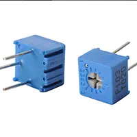
- Voltage Divider & LM431 sense battery voltage.
- TIP42C Transistor acts as a switch to connect/disconnect the load.
- Load Output receives power when the voltage is above the cutoff and disconnects when below threshold.
- Optional LED indicator shows when the load is disconnected.
Testing & Final Adjustments
Once the circuit has been put together, attach it to a 12V battery. Simulated battery dischargevariable power supplyr supply or resistive load. The cutoff threshold can be adjusted by changing the voltage divider (e.g. 11 V). Note that the TIP42C shuts the load on and the LED lights up on a decrease in voltage. Ensure that the load reconnects as the voltage on the battery increases beyond the threshold. Proper insulation and good connections should be done to prevent short-circuiting. Test in various battery conditions in an effort to ensure reliability. With greater current loading, a heat sink might be required with TIP42C. Calibration provides battery protection and increases battery life.
Frequently Asked Questions - Battery Low voltage cut off Circuit:
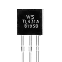
What is the role of LM431 in this circuit?
It senses the battery voltage and triggers cutoff when low.
What does TIP42C do?
Acts as a switch to disconnect the load at low voltage.
What voltage is safe for 12V batteries?
Typically around 11V for lead-acid batteries.
Can this circuit protect lithium batteries?
Yes, adjust cutoff voltage according to battery type.
Is an LED needed?
Optional, for indicating load disconnection.
Can it be used in automotive systems?
Yes, ideal for car or motorcycle battery protection.
Does it prevent over-discharge?
Yes, automatically disconnects the battery when voltage drops.
How many components are required?
Few resistors, LM431, TIP42C, and optional LED.
Is heat sink required for TIP42C?
For high current loads, yes, to prevent overheating.
Can this work in solar battery systems?
Yes, it protects 12V solar storage batteries effectively.