


LDR Working Project
Automatic light-sensing project using LDR and BC547. Switch LEDs or relays based on ambient light levels for DIY electronics and hobby projects.

LDR BC547 light-sensing project
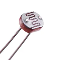
LDR operating project with BC547 measures the light intensity in the surroundings and automatically switches on LEDs or relays. It is a low-cost, easy learning project of light-sensitive transistor circuits.
light-activated relay BC547
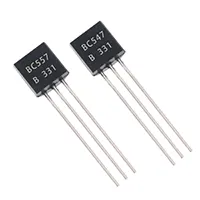
The LDR Working Project Using BC547 is an applied electronics project, which allows ambient light to automatically trigger a load (i.e., an LED or a relay). The resistance of the LDR depends on the intensity of light. When it is dark, the resistance is high, and when it is bright, the resistance is low. The project will use a transistor of type BC547 as a switch. At a point when the light becomes less than some predetermined value, the voltage across the LDR activates the conducting of the transistor, thereby turning on the other connected LED or relay. The transistor ceases to flow in bright light and puts the load OFF. The project would suit students, hobbyists, and light-sensitive circuit electronics beginners studying light-sensitive circuits, transistor switching, and automatic control systems. Parts are cheap and readily accessible. With the LDR, it is possible to adjust the series resistor by tweaking sensitivity. Examples are automatic night lights, garden lights, and lights that activate alarms or indicators.
Work / Installation (Inputs → Outputs)
- Power Input → 5–12V DC supply.
- LDR Sensor → Detects ambient light intensity.
- Voltage Divider → LDR and series resistor set threshold.
- BC547 Transistor → Switches load ON/OFF based on LDR voltage.
- Load Output → LED or relay controlled automatically.
- Installation → Assemble on PCB/breadboard; connect LDR, load, and DC supply; adjust resistor for desired sensitivity; verify proper transistor orientation.
Testing & Final Adjustments
Once assembled, apply DC voltage. Put the LDR in darkness, the BC547 transistor is supposed to be on, and switch the load on. Bring it out into the sunlight; the transistor must cease conducting, and turn off the load. Tilter sensitivity by adjusting the series resistor. Make sure that the LEDs are connected correctly, or that the relay connections are correct. Keep on testing the multiple cycles under varied lighting conditions so as to ensure that it is operating constantly. Last-minutee changes make sure that the LEDs, relays, or a little load can be reliable in switching itself automatically, and hence it is applicable in hobby electronics, automatic lighting systems, and real-world learning.