
Remote Control Tester using IR Receiver
Build a remote control tester using IR receiver and BC557 transistor. Check remote signals instantly with LED or buzzer output for DIY electronics projects.

IR remote tester BC557
An infrared receiver with a remote control tester with BC557 detects infrared rays emitted by remotes. The signal is amplified by the BC557 transistor and causes an LED or buzzer to turn on in order to show that it is working correctly.
LED remote tester circuit
Remote Control Tester with IR Receiver and BC557 enables one to test the infrared remote controls quickly. The IR signal of any remote is sensed by the IR receiver, and the signal is enhanced by the BC557 PNP transistor to power an output like an LED or buzzer. The project can be recommended to hobbyists, students, and electronics enthusiasts who seek a simple tool in order to check the functionality of a remote without additional devices. Safe operation of transistors with a resistor to limit the base current is used. The buzzer or LED output gives an immediate visual or audible signal of receiving a signal. It is safe to use on a breadboard or PCB since the circuit uses low-voltage DC. The project is also useful to those who do not know much about transistor switching, IR signal detection, and the assembly of basic circuits.
Work / Installation (Inputs → Outputs)
- Power Supply → 5–9V DC for safety.
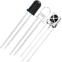
- IR Receiver Module → Detects infrared remote signals.
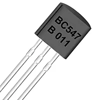
- BC557 Transistor → Amplifies the signal and switches output load.
- Resistors → Limit current to transistor and output devices.
- Output Load → LED or buzzer triggers when IR signal is received.
- Installation → Assemble components on breadboard or PCB, connect IR receiver and transistor, add LED/buzzer, and power the circuit to test remote signals.
Testing & Final Adjustments
Once assembled, press any button of the remote in the vicinity of the IR receiver. Immediately, the LED or buzzer must go off, and this is an indication that the signal is received. Change the values of the resistors in case the LED/buzzer is either too dark or not responding. Make sure that the BC557 transistor is not misplaced (emitter, base, collector). Test using several remotes to ensure universal functioning. Careful testing allows the circuit to recognize the IR signals with the highest assurance and can be a fast, easy, and efficient method of troubleshooting a remote or as a learning electronic circuit. Sensitivity of detection may be enhanced by tuning Rf values or by fine-tuning the position of the IR receiver.