RF Detector Circuit
Learn to build an RF Detector Circuit to detect hidden transmitters, wireless devices, and RF signals. Step-by-step DIY guide, diagram, and components included.

What is an RF Detector Circuit?
RF Detector Circuit is an electronic circuit that detects the RF signals in the air. When an RF signal is received, the circuit rectifies the high frequency AC signal to a DC that drives an LED or audible warning device for both visual and audio indication of a received incoming RF. It is often used to detect wireless devices within a certain range, such as wireless remote controls, bugs s or some cordless telephones.
DIY RF detector circuit
The RF Detector Circuit is an essential electronics project that you can use to detect the presence of radio frequency (RF) signal sources such as wireless/wired transmitters or wireless (RF) remote controllers. This circuit is very useful in testing for the presence of RF remotes, just to know if a remote emits the low-frequency signal.
These RF Detector Circuits can be used to detect or identify radio frequency or microwave radiation sources. Radio Frequency Detectors, which are also known as RF Detectors, are so named because they can even detect and capture the presence of any moving Radio Frequency signals that fall in their path. That it is a practical thing becomes clear by studying some of the simplest principles and integrals to receive RF, rectify, and detect. The following post is all about a straightforward RF signal detector circuit, which can be used for sensing low-range to high-range RF signals, with decent accuracy.
Components Required for the Circuit
- Small antenna (10–20 cm wire)
- NPN transistor (e.g., BC547)
- Germanium or Schottky diode (for RF detection)
- Resistors (10kΩ–100kΩ for biasing and LED current limiting)
- Capacitors (10pF–100pF for RF filtering)
- LED or buzzer for indication
- Breadboard or PCB and connecting wires
- DC power supply (3V–5V)
Working Principle of RF Detector
Signal Reception via Antenna
The antenna receives RF signals emitted by nearby transmitters, remotes, or wireless devices. These signals are high-frequency AC waves that enter the detection circuit.
Signal Detection using Diode/Transistor
A germanium or Schottky diode rectifies the RF AC into a small DC voltage. The transistor amplifies this rectified voltage, making it strong enough to activate an indicator.
Indication via LED or Buzzer
When sufficient RF energy is detected, the amplified DC signal powers an LED or buzzer. The LED lights up or buzzer sounds in presence of RF signals.
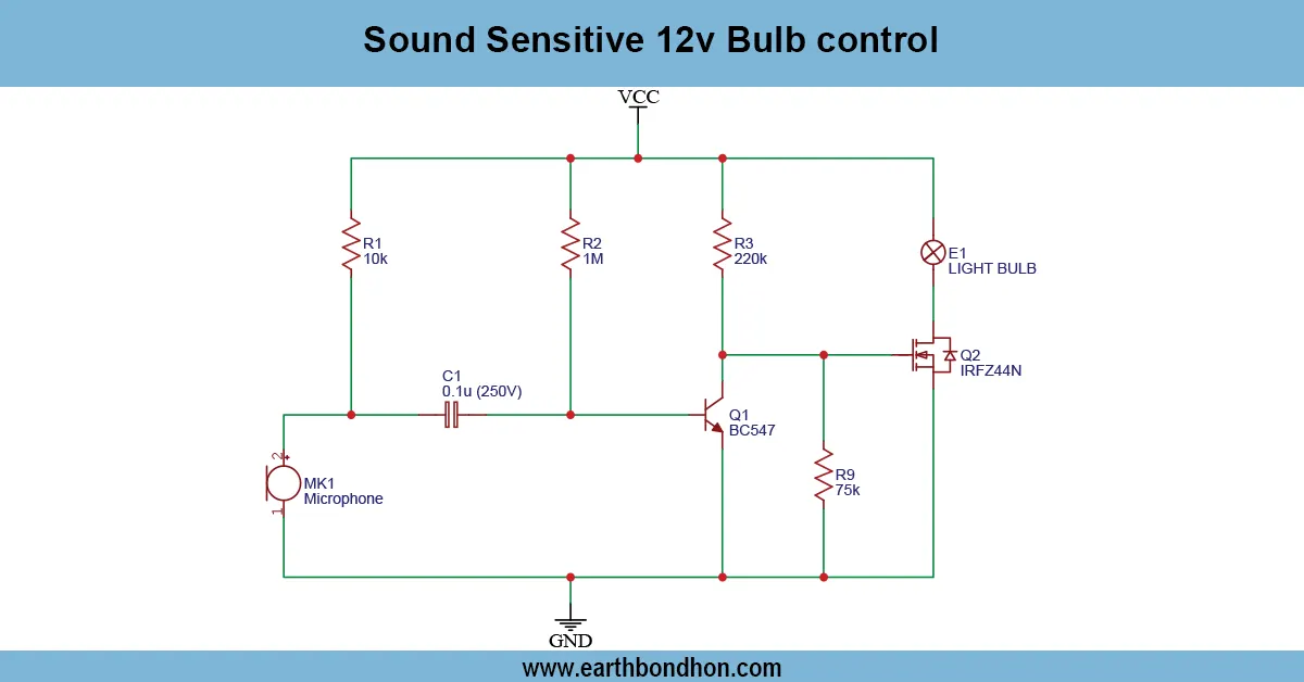
Circuit Diagram of RF Detector
Connect the antenna to the transistor base through a coupling capacitor. Place a diode between the base and ground to rectify RF signals. Connect a resistor to the transistor collector and attach an LED to the positive supply. Ground the transistor emitter. Power the circuit with 3V–5V DC. Test by bringing an RF remote or transmitter near the antenna; the LED should glow.
Step-by-Step DIY Construction Guide
- Place the transistor, diode, resistors, and capacitor on a breadboard or PCB.
- Connect the antenna to the transistor base via a capacitor.
- Attach an LED with a current-limiting resistor to the transistor collector.
- Connect a 3V–5V DC power supply.
- Test the circuit using an RF remote or wireless transmitter.
- Adjust resistor or capacitor values if the circuit sensitivity is low.
- Use a non-metallic enclosure to avoid blocking RF signals.
Applications of RF Detector Circuit
- Detect hidden wireless cameras or transmitters
- Test RF remote controls
- Educational experiments in RF and electronics
- Amateur RF hobby projects
- General RF signal detection for home or lab use
Safety Precautions
- Use low-voltage power supply to avoid damage or risk.
- Keep the antenna away from metal objects for better reception.
- Use insulated wires to prevent short circuits.
- Test in a controlled environment to reduce unwanted interference.
Troubleshooting Common Issues
No LED Indication
Check the power supply and ensure the transistor orientation is correct. Verify that the diode is connected properly for rectification.
False Triggering
Reduce interference from nearby devices. Adjust capacitor values or add shielding for better stability.
Weak Signal Detection
Use a longer antenna for increased sensitivity. Experiment with resistor/capacitor values to increase gain.