Float switch connection diagram:
This diagram shows how to make Float switch connection diagram. In this circuit diagram, we use a DP MCB ( Double Pole Miniature Circuit Breaker ), 2 Magnetic contactors, 2 single Phase motors, and a float switch. First, we need to input power to DP MCB, then from DP MCB to input power to all magnetic contactors, then from the contactor to connect power to all motors and the float switch. Now this circuit is ready for use. If you want to know more about this circuit please check our youtube video below the link.
Advertisements
Diagram of Float switch connection diagram:

Components needed For this Project:
You can get the components from any of the sites below:
- Magnetic Contactor 40A [See Buy Click Amazon]
- DP MCB 20A [See Buy Click Amazon]
- Float Switch Water Level Controller [See Buy Click Amazon]
- Single Phase Motor (1 HP) [See Buy Click Amazon]
*Please note: These are affiliate links. I may make a commission if you buy the components through these links. I would appreciate your support in this way!
Advertisements
Components used to make the Float switch connection diagram:
01. Magnetic Contactor:

A magnetic contactor is an electromagnetic switching device. It is generally used for controlling 3-phase Motors. The operation of a magnetic contactor is similar to that of a Relay. but a relay is used for low-power or low-voltage connections, and a magnetic contactor is used for high-power or high-voltage connections. As soon as the supply is applied to the magnetic contactor coil. its normally open contacts are closed and normally closed contacts are opened and the associated devices are also operated. This is how a magnetic contactor works.
02. DP MCB:
DP MCB In 2 Pole MCB, switching & protection is affected in phases and the neutral. A Double Pole or DP Switch is a Switch that Controls 2 Circuits at the same time. In terms of Residential Switching, this Normally means it Switches the live and Neutral at the same time. In Layperson Terms, Double Pole switches or DP Switches are Exclusively Designed to Control 2 Different Electrical Circuits at the same time, which allows the Appliances to Isolate safely and reliably. Fan or light Combinations and Medical Equipment are some of the many applications for DP Electrical Switches and Electrical components.

03. Float Switch:
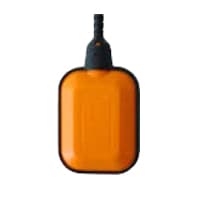
A Float Switch is a type of Level Sensor Device Used to Detect the level of liquid within a tank. The Switch May be Used to Control a Pump, as an Alarm, as an Indicator, or to Control Other Devices. 1 type of Float Switch Uses a Mercury Switch Inside a Hinged float. Another common type is a Float Switch That Raises a rod to Actuate a Microswitch. One Pattern Uses a reed Switch Mounted in a Tube Float, Containing a Magnet, Surrounding the Tube, and Guided by it.
04. Single Phase Motor:
A Single-Phase Motor is an Electrically-Powered Rotary Machine That Can Turn Electric Energy into Mechanical Energy. It Works by Using a Single-Phase Power Supply. Single-phase Motors Are Used in Equipment And Machines That Are Smaller in Size And Require Lower Horsepower. This Includes Equipment Such As Refrigerators, Pumps, Compressors, Fans, and Portable Drills. Single-phase motors Have a Similar Construction to The 3-phase Motor, Including an AC Winding That is Placed on The Stator And Short-Circuited Conductors That are Placed in a Cylindrical Rotor.

Thank You for visiting the website. Keep visiting for more Updates.
Frequently asked questions
One pattern uses a reed switch mounted in a tube; a float, containing a magnet, surrounds the tube or is guided by it. When the float raises the magnet to the reed switch sensor it closes. Several reeds could be mounted in the tube for different level indications by one assembly.
A float switch is a type of level sensor, a device used to detect the level of liquid within a tank. One pattern uses a reed switch mounted in a tube; a float, containing a magnet, surrounds the tube and is guided by it. When the float raises the magnet to the reed switch sensor it closes”.
The float CSS property places an element on the left or right side of it as a container, allowing text or inline elements to wrap around it. The element is removed from the normal flow of the page, though still remaining part of the flow (in contrast to an absolute positioning).
The float of the switch location depends on the orientation of your HVAC equipment. For horizontal units, the float switch would be located in the secondary drain pan. For horizontal units without a secondary drain pan and vertical units, the float switch would be on the drainpipe.
The float data types are used to store the positive and negative numbers with a decimal point, like 35.3, -2.34, and 3597.34987.
Read more Single Phase Wiring
What is a kilowatt-hour (kWh) | kwh formula | What does kwh mean
Introduction to Electrical Units and CircuitskW and kWh on your electricity bill As your home uses electricity during...
What is the Difference Between kVA | What does KVA mean | kVA formula
Difference Between KVA ExplainedWhat does KVA Mean? There are technical terms aplenty when it comes to generators, and...
Power Factor | Power Unit | Energy | Electricity Unit
Power factor definition | Calculating Power FactorPower Factor Values In a purely resistive circuit, the power factor...
0 Comments