Flowmeter With Relay wiring:
This diagram shows how to make Flowmeter With Relay wiring. In this circuit, we use a DP MCB ( Double Pole Minature Circuit Breaker ), a selector switch, a relay, two magnetic contactors, two overload relays, a flow meter, and a timer. First, we need to connect the DP MCB with the power source, then connect the selector switch with the DP MCB, then connect the relay and timer with the DP MCB, then connect the contactor and overload with the relay and lastly need to connect the flowmeter with DP MCB and contactor. Now this circuit is ready to use.
Advertisements
Diagram of Flowmeter With Relay wiring:

Components needed For this Project:
You can get the components from any of the sites below:
- DP MCB 20A [See Buy Click Amazon]
- Magnetic Contactor 40A [See Buy Click Amazon]
- 8 Pin Timer 220V AC [See Buy Click Amazon]
- Selector Switch (220V AC) [See Buy Click Amazon]
- 8 Pin Relay (220V AC) [See Buy Click Amazon]
- Motor Protector Overload [See Buy Click Amazon]
- Flow Meter [See Buy Click Amazon]
*Please note: These are affiliate links. I may make a commission if you buy the components through these links. I would appreciate your support in this way!
Advertisements
Components used to make the Flowmeter With Relay wiring:
01. DP MCB:

DP MCB In 2 Pole MCB, switching & protection is affected in phases and the neutral. A Double Pole or DP Switch is a Switch that Controls 2 Circuits at the same time. In terms of Residential Switching, this Normally means it Switches the live and Neutral at the same time. In Layperson Terms, Double Pole switches or DP Switches are Exclusively Designed to Control 2 Different Electrical Circuits at the same time, which allows the Appliances to Isolate safely and reliably. Fan or light Combinations and Medical Equipment are some of the many applications for DP Electrical Switches and Electrical components.
02. Magnetic Contactor:
A magnetic contactor is an electromagnetic switching device. It is generally used for controlling 3-phase Motors. The operation of a magnetic contactor is similar to that of a Relay. but a relay is used for low-power or low-voltage connections, and a magnetic contactor is used for high-power or high-voltage connections. As soon as the supply is applied to the magnetic contactor coil. its normally open contacts are closed and normally closed contacts are opened and the associated devices are also operated. This is how a magnetic contactor works.

03. Timer:

A timer is a type of time-switching device that controls and controls Electrical circuits and electrical and electronic devices through time setting (on/off). The timer is basically 8-pin. Like other controlling devices the timer has a coil and when this coil is magnetized, the timer works on/off. The timer has 2 common ends and each common end has normally close and normally open options. When the timer is set by time, the timer trips at the end of that time and turns the common is normally closed (on) to open (off) and normally open (off) to close (on). This is how the timer works.
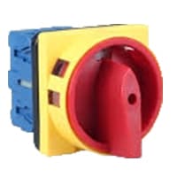
04. Selector Switch:
A Mechanical Switch That can be rotated Left, right, or center to open or close the Electrical contacts is known as a Selector switch. The Main Function of This Selector Switch is to Control Devices and also to Switch Between a Minimum of 2 or Above Electrical Circuits. The Perfect Used for Selector Switch is When Used for Controlling the Output of a Device. We know that a Selector switch is Used to control the electrical current flow in a Circuit it can also be used to both Initiate and inhibit the Current Flow.
05. 8-Pin Relay:
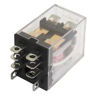
The most popular relay for automation work is the 8 Pin Relay. The 8-pin relay has a DC or AC coil as the main part. which is connected to two pins. There are two common parts. Underneath a Common part are a NO and an NC part. No part is normally open with a common part and the NC part is normally closed. The timer base used for automation is the same as the 8-relay base. That is, switching can be done using the timer base. This is basically how a relay switch works for the relay.
06. Overload Relay:
Overload Protection is Protection Against a Running Overcurrent That Would Cause Overheating of The Protected Equipment. Hence, An Overload is Also a Type of Overcurrent flow. Overload Protection Typically Operates on an Inverse Time curve where the Tripping Time Becomes less as the Current Increases. This Overload Protector is an Essential Component for Many Sockets Power Systems. The Top-Quality Overload Protector can Effectively Protect Electrical Products from Power Surges.

07. Flowmeter:
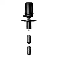
Water flow meters are devices used to measure the volume or mass of fluid that passes through a pipe for water. They are commonly used in water flow treatment and distribution systems, irrigation, and industrial processes. There are several types of water flow meters set, including positive displacement meters, turbine meters, ultrasonic meters, and magnetic meters. A water flow meter measures the total volume of fluid that has passed through a pipe over a certain time. A water flow sensor, on the other hand, measures the velocity of the fluid flow at a specific point in time. It is mainly used to monitor the flow rate in real-time, to detect any changes or irregularities in the water flow, and to regulate or control the flow as needed.
Thank You for visiting the website. Keep visiting for more Updates.
Frequently asked questions
When an electrically conductive fluid flows in the pipe, an electrode voltage E is induced between a pair of electrodes placed at right angles to the direction of the magnetic field. The electrode of the voltage is directly proportional to the average fluid velocity V.
Two common types of mass flow meters are Coriolis and thermal mass. A mass flow meter measures the mass of a fluid by its inertia as it passes through a vibrating tube equipped with sensors at the inlet and outlet. The vibration of the tube of the causes oscillation is proportional to the mass of the fluid.
Thermal mass flowmeters generally use combinations of heated elements and the temperature of the sensors to measure the difference between static and flowing heat transfer to a fluid or infer its flow with a knowledge of the fluid's specific heat and density. The fluid temperature is also measured or compensated for.
Water flow meters are used to measure the volume of the water used in commercial and residential buildings. The water is supplied to homes or offices via a public water supply system. Water meters may also be used at water sources and throughout the water system to calculate the flow rate of a part of the system.
Other flowmeters are meant to count the total amount in liters of fluid that has gone them (such as 100 liters). Most flowmeters have 3 parts, the primary device, a transducer, and a transmitter. The work of the transducer is to sense the fluid passing of the primary device.
Read more Single Phase Wiring
What is a kilowatt-hour (kWh) | kwh formula | What does kwh mean
Introduction to Electrical Units and CircuitskW and kWh on your electricity bill As your home uses electricity during...
What is the Difference Between kVA | What does KVA mean | kVA formula
Difference Between KVA ExplainedWhat does KVA Mean? There are technical terms aplenty when it comes to generators, and...
Power Factor | Power Unit | Energy | Electricity Unit
Power factor definition | Calculating Power FactorPower Factor Values In a purely resistive circuit, the power factor...
0 Comments