Generator Transfer Switch Wiring:
This diagram shows how to connect the generator transfer switch wiring. In this circuit diagram, we just use a power generator, a 3-pin power socket, 2 plugs, a DP MCB ( Double Pole Miniature Circuit Breaker ), six SP MCB ( Single Pole Miniature Circuit Breaker ), an automatic transfer or changeover switch. This diagram is very easy to connect. If you want to make this circuit easily please check our youtube video in the below link for more information.
Advertisements
Diagram of Generator Transfer Switch Wiring:

Components needed For this Project:
You can get the components from any of the sites below:
- Single Phase Generator 2000W[See Buy Click Amazon]
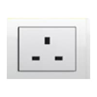
- Gang Socket [See Buy Click Amazon]
- DP MCB 20A [See Buy Click Amazon]
- SP MCB 10A [See Buy Click Amazon]
- Dual Power ATS Generator Changeover [See Buy Click Amazon]
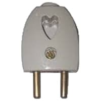
- 2 Pin Plug 220V AC [See Buy Click Amazon]
*Please note: These are affiliate links. I may make a commission if you buy the components through these links. I would appreciate your support in this way!
Advertisements
Components used to make the Generator Transfer Switch Wiring:
01. Power Generator:
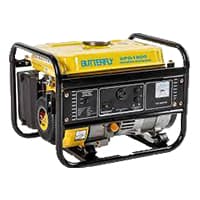
An electric generator is a type of Electrical device that converts mechanical energy or power into electrical energy or power. However, dynamo generally refers to generators only. The first generator built was called a dynamo. This electrical device makes this conversion using the principle of kinetic electromagnetic energy generation. According to Farad is principle of electromagnetic induction, a dynamic electromagnetic induction is induced in a conductor when it passes through a magnetic flux.
02. 3-Pin Socket:
A Power Socket is a Device to Which Electrical Devices Can Be Connected to Receive the Electric Current Required For Their Operation. Connected by a System of Cables to a Power Source, Usually, an Electricity Generation Facility operated by an energy Production company, generally has no moving parts. Instead, it contains metal strips that make contact with the prongs of an Electric plug inserted into the socket. It is Through these Contacts That the Electric current is Transmitted. Electrical Devices that connect to a Power Source Through a Power Socket are Considered to be Portable Because they can easily be Connected and Disconnected From the Power Source.
03. DP MCB:

DP MCB In 2 Pole MCB, switching & protection is affected in phases and the neutral. A Double Pole or DP Switch is a Switch that Controls 2 Circuits at the same time. In terms of Residential Switching, this Normally means it Switches the live and Neutral at the same time. In Layperson Terms, Double Pole switches or DP Switches are Exclusively Designed to Control 2 Different Electrical Circuits at the same time, which allows the Appliances to Isolate safely and reliably. Fan or light Combinations and Medical Equipment are some of the many applications for DP Electrical Switches and Electrical components.
04. SP MCB:
In single-pole MCB, Switching and protection are Affected in only one Phase. Single phase supply to break the phase only. A single Pole breaker is Typically used with 120-volt Circuits, and a 6-20 amps Miniature Circuit Breaker. They are constructed with one Line Wire and one Neutral wire. A Single Pole switch is the most basic General-Purpose switch that you use to Control a light or another device from one location. These Switches have 2 Brass-Colored screw Terminals Connected to the hot Power source wires. Pole refers to the number of Circuits Controlled by the Switch SP Switches Control only one Switch Electrical Circuit.

05. Changeover Switch:

Change over switch is a medium of line transfer that is used in industry. Every industry has a supply line using change-over switches to supply power. A Changeover Switch is an Electrical Switch That Allows a load to be Changed from one Electrical Source to Another and vice Versa, Either Manually or Automatically. A Changeover Switch is specially made to transfer a house is electricity from the Normally used Commercial Power supply grid to a more local Generator when a power Outage Occurs.
06. 2-Plug:
2-Pole Means That the Device Plug is not Earthed and it Normally Has 2-Pins That Transmit Electricity. Originally, all Electrical Devices were Fitted with 2-pole Plugs, Which Means that the Devices were not earthed and that all main Sockets were Constructed for 2-pole plugs system. 2-pin Plugs Consist of 2 flat or Round Pins with one Called “hot” “live” or "line" and the Other Called “neutral”. When Connected to an Electric Circuit, the Current Flows From the live Pins Through The Copper Conductor and into the Device system.
Thank You for visiting the website. Keep visiting for more Updates.
Frequently asked questions
The installation of a generator transfer switch is a complex electrical task that should be handled by a licensed electrician. Attempting to install a transfer switch yourself can be dangerous and may result in electrical hazards, code violations, and damage to your electrical system.
When the generator system is required to be separately grounded at the site, a transfer switch with a switchable neutral should be selected. With a switched neutral, the generator set can be wired as a separate and derived system to the power supply load and normal power supply.
YES, two or more ASCO transfer switches can be connected to a common generator and any transfer switch can start the generator. The generator and start wires must be connected to the “engine and start contacts” of one of the Project system transfer switches.
Transfer switches, both automatic and manual, provide fast access to power supply for critical functions in the event of an outage. Without a transfer switch, you have to manually connect your generator to the Currenttlou equipment you want to power supply. This is much less efficient and less power supply effective.
This category of inverter generator can be connected directly to your electrical panel with a safety device called a transfer and switch, which CR strongly recommends. That allows the generator to power supply entire circuits diagram in your home rather than requiring you to plug in individual electronics with extension cords.
Read more Single Phase Wiring
What is a kilowatt-hour (kWh) | kwh formula | What does kwh mean
Introduction to Electrical Units and CircuitskW and kWh on your electricity bill As your home uses electricity during...
What is the Difference Between kVA | What does KVA mean | kVA formula
Difference Between KVA ExplainedWhat does KVA Mean? There are technical terms aplenty when it comes to generators, and...
Power Factor | Power Unit | Energy | Electricity Unit
Power factor definition | Calculating Power FactorPower Factor Values In a purely resistive circuit, the power factor...
0 Comments
Trackbacks/Pingbacks