Main switch and selector switch wiring:
This diagram shows the Main switch and selector switch wiring. In this circuit, we use a main switch, a selector switch, a magnetic contactor with overload, a DP MCB ( Double Pole Minature Circuit Breaker ), and a Compressor. First, we need to connect the DP MCB with a power source, then connect the magnetic connector with DP MCB, then connect the selector switch and main switch. Lastly, we need to connect the compressor to the circuit breaker.
Advertisements
Diagram of Main switch and selector switch wiring:

Components needed For this Project:
You can get the components from any of the sites below:
- Main Switch [See Buy Click Amazon]
- Selector Switch (220V AC) [See Buy Click Amazon]
- Magnetic Contactor 40A [See Buy Click Amazon]
- Motor Protector Overload [See Buy Click Amazon]
- DP MCB 20A [See Buy Click Amazon]
- Air Compressor Max 150 PSI Pressure[See Buy Click Amazon]
*Please note: These are affiliate links. I may make a commission if you buy the components through these links. I would appreciate your support in this way!
Advertisements
Components used to make the Main switch and selector switch wiring:
01. Main Switch:
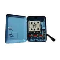
The Main Switch is Connected to the live and Neutral Wires. It is Used to Cut the Connections of the Live Wire as well as the Neutral Wire Simultaneously from the Main Supply. The main switch Isolates the Electrical supply from the whole installation so that it can be turned off for Servicing or Maintenance. It also provides overload protection for the mains cables (on newer switchboards) so that they will trip if the cable is Drawing too Much Power.
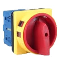
02. Selector Switch:
A Mechanical Switch That can be rotated Left, right, or center to open or close the Electrical contacts is known as a Selector switch. The Main Function of This Selector Switch is to Control Devices and also to Switch Between a Minimum of 2 or Above Electrical Circuits. The Perfect Used for Selector Switch is When Used for Controlling the Output of a Device. We know that a Selector switch is Used to control the electrical current flow in a Circuit it can also be used to both Initiate and inhibit the Current Flow.
03. Magnetic Contactor:

A magnetic contactor is an electromagnetic switching device. It is generally used for controlling 3-phase Motors. The operation of a magnetic contactor is similar to that of a Relay. but a relay is used for low-power or low-voltage connections, and a magnetic contactor is used for high-power or high-voltage connections. As soon as the supply is applied to the magnetic contactor coil. its normally open contacts are closed and normally closed contacts are opened and the associated devices are also operated. This is how a magnetic contactor works.
04. Overload Relay:
Overload Protection is Protection Against a Running Overcurrent That Would Cause Overheating of The Protected Equipment. Hence, An Overload is Also a Type of Overcurrent flow. Overload Protection Typically Operates on an Inverse Time curve where the Tripping Time Becomes less as the Current Increases. This Overload Protector is an Essential Component for Many Sockets Power Systems. The Top-Quality Overload Protector can Effectively Protect Electrical Products from Power Surges.

05. DP MCB:

DP MCB In 2 Pole MCB, switching & protection is affected in phases and the neutral. A Double Pole or DP Switch is a Switch that Controls 2 Circuits at the same time. In terms of Residential Switching, this Normally means it Switches the live and Neutral at the same time. In Layperson Terms, Double Pole switches or DP Switches are Exclusively Designed to Control 2 Different Electrical Circuits at the same time, which allows the Appliances to Isolate safely and reliably. Fan or light Combinations and Medical Equipment are some of the many applications for DP Electrical Switches and Electrical components.
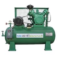
06. Compressor:
Air is Compressed by air Compressors. Air Compressors draw in Air at an Inlet Valve, They Then Compress The Air to The Required Volume And Release The Pressurized air through the discharge Valve into a Storage Tank. Air Compressors Work by Forcing Atmospheric air Under Pressure to Create Potential Energy That Can be Stored in a Tank for Later used. Just like an Open Balloon. The Pressure Builds up When the Compressed Air is Deliberately Released. Converting The Potential Energy into Usable Kinetic Energy is used.
Thank You for visiting the website. Keep visiting for more Updates.
Frequently asked questions
The main Switch allows us to turn off or on the electricity supply to our home. The Main switch distributes the current flow all over the house and takes care of all the fuses or wires in it. It is the main connecting link between external of the supply and household wiring. We might have more than 1 main switch.
A residential main service panel contains either circuit diagram breakers or fuses and is usually located in a utility area. It would be easily accessible but away from the main traffic flow in the house. The panel may be in the garage or basement.
An MCB is an automatically operated electrical switch. Miniature circuit diagram breakers are intended to prevent damage to an electrical circuit as a result of excess current flow. They are designed to trip during an overload or short circuit diagram to protect against electrical faults and equipment failure.
Yes, MCB could be used as a manual ON/OFF switch. Since the short circuit diagram and overload protection are built into the MCB and come with no option to disable, the MCB could operate to open the circuit diagram in case of a fault downstream.
A Selector Switch is a device used to start and stop current flowing along a circuit diagram or multiple circuits. Devices in this family have an actuator and Knob that turns back and forth along a center axis point but have a predetermined number of stopping positions (2 to 7).
Read more Single Phase Wiring
What is a kilowatt-hour (kWh) | kwh formula | What does kwh mean
Introduction to Electrical Units and CircuitskW and kWh on your electricity bill As your home uses electricity during...
What is the Difference Between kVA | What does KVA mean | kVA formula
Difference Between KVA ExplainedWhat does KVA Mean? There are technical terms aplenty when it comes to generators, and...
Power Factor | Power Unit | Energy | Electricity Unit
Power factor definition | Calculating Power FactorPower Factor Values In a purely resistive circuit, the power factor...
0 Comments