Single Phase Full House Wiring:
This diagram shows how to make Single Phase Full House Wiring. In this circuit, we use two ceiling fans, two lights, some switches, two fan regulators, some power sockets, a DP MCB ( Double Pole Miniature Circuit Breaker ), an SPD ( Surge Protection Device ), an RCBO ( Residual current operated Circuit Breaker with Overcurrent protection ), 3 SP MCB ( Single Pole Miniature Circuit Breaker ). This circuit is very simple and easy to make, if you want to know more about this circuit please stay with our website and check our youtube video below the post.
Advertisements
Diagram of Single Phase Full House Wiring:

Components needed For this Project:
You can get the components from any of the sites below:
- DP MCB 32A [See Buy Click Amazon]
- DP SPD 20KA [See Buy Click Amazon]
- DP RCBO 32A [See Buy Click Amazon]
- SP MCB 20A [See Buy Click Amazon]
- Gang Socket [See Buy Click Amazon]
- Fan Regulator [See Buy Click Amazon]
- Ceiling Fan 56-Inch [See Buy Click Amazon]
- CFL Light [See Buy Click Amazon]
- Fluorescent Tube [See Buy Click Amazon]
*Please note: These are affiliate links. I may make a commission if you buy the components through these links. I would appreciate your support in this way!
Advertisements
Components used to make the Single Phase Full House Wiring:
01. DP MCB:

DP MCB In 2 Pole MCB, switching & protection is affected in phases and the neutral. A Double Pole or DP Switch is a Switch that Controls 2 Circuits at the same time. In terms of Residential Switching, this Normally means it Switches the live and Neutral at the same time. In Layperson Terms, Double Pole switches or DP Switches are Exclusively Designed to Control 2 Different Electrical Circuits at the same time, which allows the Appliances to Isolate safely and reliably. Fan or light Combinations and Medical Equipment are some of the many applications for DP Electrical Switches and Electrical components.
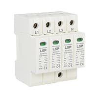
02. SPD:
The ability of an SPD to limit overvoltage in the Electrical distribution network by diverting the surge current is the surge-protective component, the mechanical structure of the SPD, and the connection to the electrical distribution network. A surge protection device SPD is a component of an electrical installation protection system. This device is connected to the power supply in parallel with the load circuit it is intended to protect. It can be used at all levels of the Power Supply Network. It is widely used in overvoltage protection.
03. RCBO:
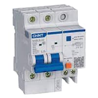
An RCBO protects Electrical equipment against 2 types of faults. Residual current and over current. Residual current. or earth leakage as it is sometimes referred to, occurs when there is a break in the circuit which can be caused by faulty electrical wiring or if the wire is accidentally cut. When there is a break in the circuit which may be due to faulty electrical wiring or accidental cutting of the wire. To prevent the current from being redirected and causing an electric shock. the RCBO current breaker stops it.
04. SP MCB:
In single-pole MCB, Switching and protection are Affected in only one Phase. Single phase supply to break the phase only. A single Pole breaker is Typically used with 120-volt Circuits, and a 6-20 amps Miniature Circuit Breaker. They are constructed with one Line Wire and one Neutral wire. A Single Pole switch is the most basic General-Purpose switch that you use to Control a light or another device from one location. These Switches have 2 Brass-Colored screw Terminals Connected to the hot Power source wires. Pole refers to the number of Circuits Controlled by the Switch SP Switches Control only one Switch Electrical Circuit.

05. Power Socket:
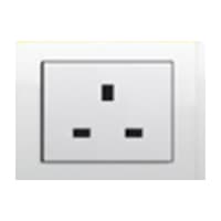
A Power Socket is a Device to Which Electrical Devices Can Be Connected to Receive the Electric Current Required For Their Operation. Connected by a System of Cables to a Power Source, Usually, an Electricity Generation Facility operated by an energy Production company, generally has no moving parts. Instead, it contains metal strips that make contact with the prongs of an Electric plug inserted into the socket. It is Through these Contacts That the Electric current is Transmitted. Electrical Devices that connect to a Power Source Through a Power Socket are Considered to be Portable Because they can easily be Connected and Disconnected From the Power Source.
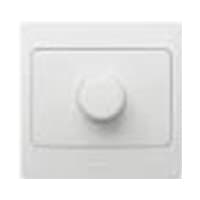
06. Fan Regulator:
A Fan Speed Controller Controls The Voltage Across the Fan and Therefore Indirectly Controls its speed 220v AC line. A ceiling Fan Speed Regulator Actually Measures and Regulates the Speed of the Fan Using its Tachometer. Fan Speed is Controlled with Thyristor or Transformer Speed Controllers for Ceiling fans, and table fans. the fan is Controlled by a Capacitor, and the Voltage across the fan Determines the fan speed. A Speed Control loop Can be Implemented That is Independent of Manufacturing Variances and Wear on The Fan control system.
07. Ceiling Fan:
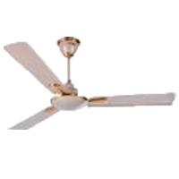
A Ceiling Fan is a fan Mounted on the Ceiling of a Room or space, Usually, Electrically Powered, That Uses hub-mounted Rotating Blades to Circulate air flow. They cool people effectively by increasing speed. It Doesn not Cool the Air Temperature — we Feel Cooler Because the Fan Moves the Air Around Us, a Process Called Evaporative Cooling. Evaporative Cooling Works like this: A cold day will feel Even Cooler if There is a Breeze Because of the wind Chill Factor.
08. CFL Light:
CFL stands for Compact Fluorescent Lamp which is an improved version of tube lights of earlier days. Like tube lights, it is a vacuum glass tube with fluorescent powder coating which is not as long and straight as tube lights but curved/twisted compact, or small in size. Like a tube light, it has electrodes or filaments at both ends. But in this case, instead of a choke, there is an electronic circuit that drives the Compact Fluorescent Lamp. Because the red wave is less in the light of the Tubelight and Compact Fluorescent Lamp, the object looks a little pale or the correct color of the object does not appear.

09. Fluorescent Tube:
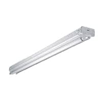
The structural element of the tube light is an airtight glass tube which is commonly called a sealed glass tube. This tube is airtight. The tube fills with a small amount of mercury. Also contains an inert gas (usually argon). The tube inside is also coated with phosphorus. That is why it looks white. There are 2 electrodes at both ends of the tube which can create an electric field between them. These 2 electrodes are again connected to an electrical circuit. Electrical This circuit usually consists of a starter switch and ballast. This circuit is connected to our AC supply. The difference between ordinary incandescent bulbs and fluorescent bulbs (which we call tube lights) is the process of activating or exciting the atoms. In normal bulbs, the atoms are activated by heating. In fluorescent bulbs. this is done through accelerated chemical reactions.
Thank You for visiting the website. Keep visiting for more Updates.
Read more Single Phase Wiring
What is a kilowatt-hour (kWh) | kwh formula | What does kwh mean
Introduction to Electrical Units and CircuitskW and kWh on your electricity bill As your home uses electricity during...
What is the Difference Between kVA | What does KVA mean | kVA formula
Difference Between KVA ExplainedWhat does KVA Mean? There are technical terms aplenty when it comes to generators, and...
Power Factor | Power Unit | Energy | Electricity Unit
Power factor definition | Calculating Power FactorPower Factor Values In a purely resistive circuit, the power factor...
0 Comments