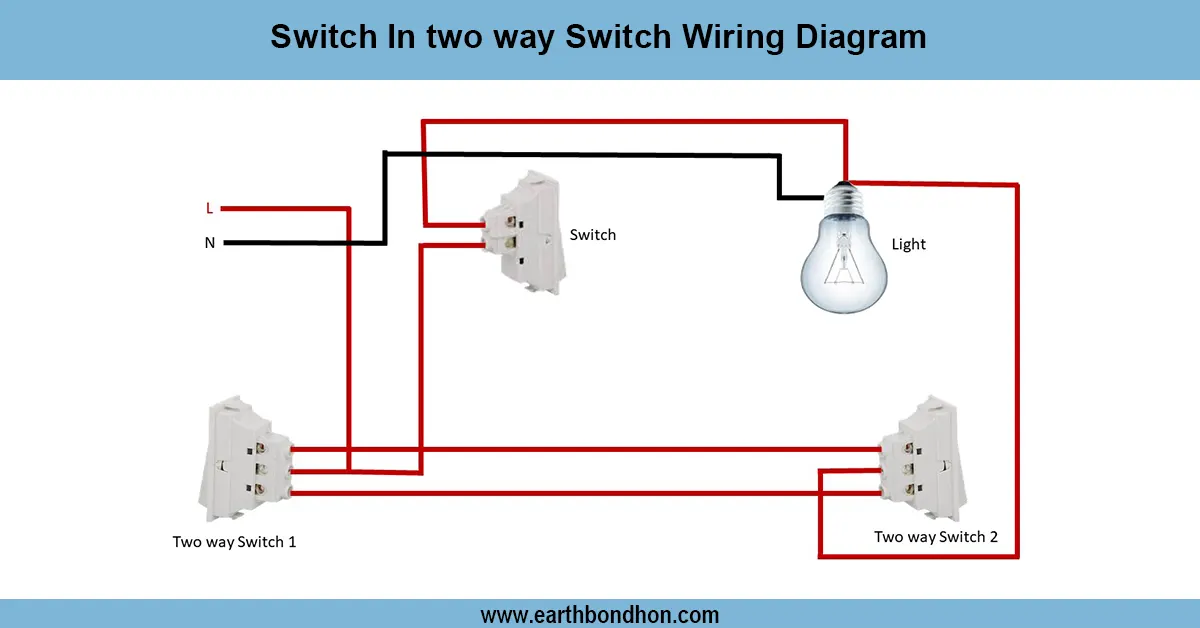
Voltmeter connection circuit diagram
Voltmeters are connected in parallel with whatever device's voltage is to be measured. A parallel connection is used because objects in parallel experience the same potential difference.

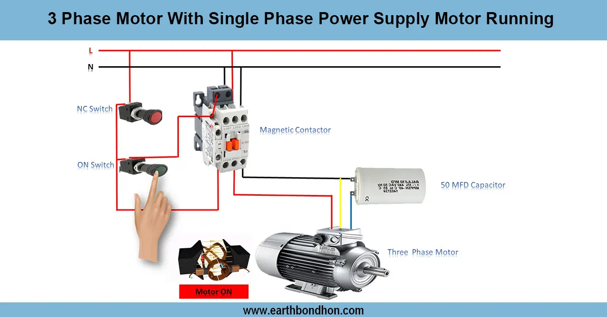
voltmeter wiring diagram
Voltmeter is always used in parallel to the circuit points in order to measure the potential difference. This is used to measure the voltage correctly without affecting the current. Connect the voltmeter between live and neutral in a single-phase; or any two phases or between a phase and neutral in a three-phase system. It is safe to express because of proper wiring, which eliminates damages.
Formula & Table Summary:
Formula: V = I × R (Ohm’s Law for calculating voltage)
Summary: Voltmeter connection is parallel to load, never in series. It measures voltage without significantly affecting the circuit's resistance or current.
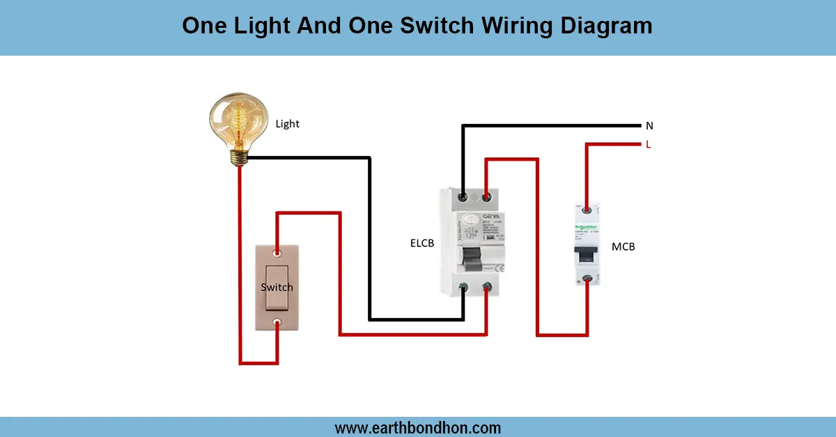
voltmeter connection procedure
Voltmeter connection diagram represents how to interconnect voltmeter with an electrical load or circuit to precisely detect voltage without altering current flow when the voltmeter is connected. Proper wiring with any kind of power be it, single-phase or three-phase will bring quality and safe voltage measurements. It is always an important aspect of connecting the voltmeter between the two points at which the voltage needs to be measured. On single-phase systems this is usually between the live wire and the neutral wire but with three-phase systems it can be either line-to-line or line-to-neutral, depending on the need. Voltmeter understanding is very critical in troubleshooting, checking the load and/or maintenance activities when it comes to electrical systems. By applying an adequate diagram, an electrician or DIY enthusiast will not make a wiring mistake that may destroy the meter or the system.
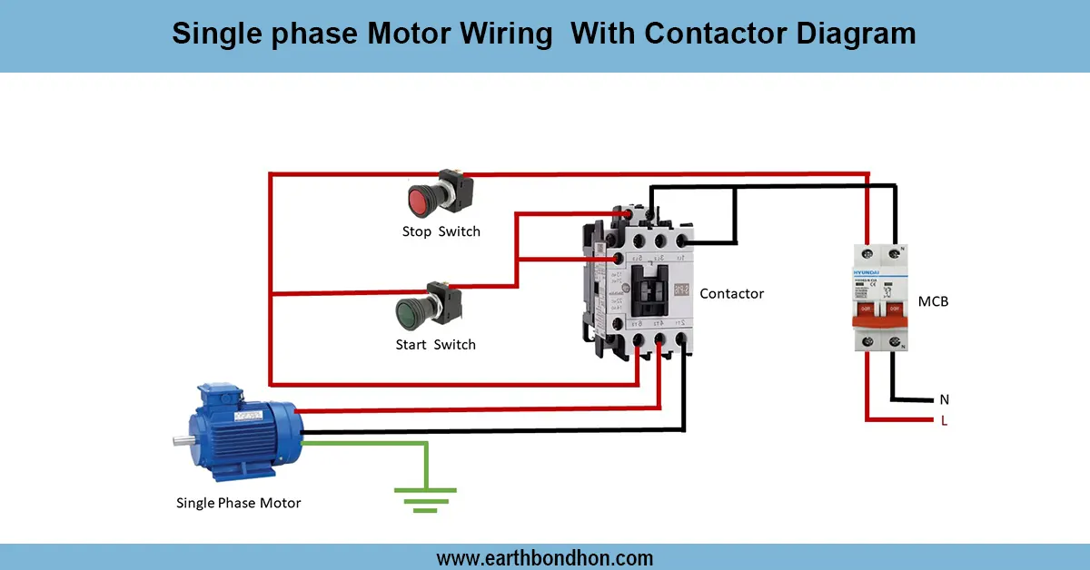
voltmeter connection procedure
| System Type | Connection Points | Purpose |
|---|---|---|
| Single Phase | Live & Neutral | Measure supply voltage |
| Three Phase | Phase to Phase | Measure line voltage |
Frequently Asked Questions - Voltmeter connection circuit diagram:
What is the correct way to connect a voltmeter?
Always connect a voltmeter in parallel with the circuit or component.
Can a voltmeter be connected in series?
No, voltmeters must be connected in parallel to measure voltage correctly.
Where to connect voltmeter in single phase?
Across live and neutral terminals.
Where to connect voltmeter in three phase?
Between two phases or between a phase and neutral.
Why connect voltmeter in parallel?
It measures voltage without changing the circuit current.
Can I use a voltmeter for DC voltage?
Yes, but ensure the voltmeter is rated for DC measurement.
What happens if voltmeter is connected in series?
It will not measure voltage correctly and may affect circuit operation.
Can digital and analog voltmeters be connected the same way?
Yes, both types are connected in parallel.
What is the symbol of a voltmeter in diagrams?
A circle with the letter 'V' inside.
What safety precautions should I follow?
Turn off power before connecting and ensure meter rating matches system voltage.