3 phase preventer wiring:
This Diagram shows 3-phase preventer wiring. In this circuit, we use a three-phase preventer, an NC Switch, an NO Switch, a magnetic contactor, and a three-phase motor. This circuit diagram is very simple and easy to make. If you want to know more details about this circuit please check our youtube video below the post. Please stay with our website for more updates about electrical electronics and robotics projects gadgets and circuits.
Advertisements
Diagram of 3 phase preventer wiring:

Components needed For this Project:
You can get the components from any of the sites below:
- Magnetic Contactor 40A [See Buy Click Amazon]
- [singlephase_preventer]
- Push Button NC Switch [See Buy Click Amazon]
- Push Button NO Switch [See Buy Click Amazon]
- 3 Phase Motor (5 HP) [See Buy Click Amazon]
*Please note: These are affiliate links. I may make a commission if you buy the components through these links. I would appreciate your support in this way!
Advertisements
Components used to make the 3 phase preventer wiring:
01. Magnetic Contactor:

A magnetic contactor is an electromagnetic switching device. It is generally used for controlling 3-phase Motors. The operation of a magnetic contactor is similar to that of a Relay. but a relay is used for low-power or low-voltage connections, and a magnetic contactor is used for high-power or high-voltage connections. As soon as the supply is applied to the magnetic contactor coil. its normally open contacts are closed and normally closed contacts are opened and the associated devices are also operated. This is how a magnetic contactor works.
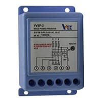
02. Phase Preventer:
Single Phasing Preventer is Used for The Protection And Burnouts of Pumps And Motors Against Phase Unbalance, Missing, and Negative Phase Sequences. A Single-Phase Preventer Relay is a Control Device That Detects Any Failure in Phase Supply. Energizes Its Auxiliary Relay Contacts system. This Contact is Then Given to The PLC Which Turns Off its outputs through programming written for the computer. We Use a Single-Phase Preventer To Protect The Induction Motor From a Single-Phasing Fault.
03. NC Switch:

An NC (Normally Closed) Push Button is a Push Button That, In Its Default State, Makes Electrical Contact With The Circuit. An NC (Normally Closed) Push Button is a Push Button that, in its Default State, Makes electrical Contact With the Circuit. When The Button Is Pressed Down, The Switch no Longer Makes Electrical Contact And The Circuit is Now Open. When The Button is Not Pressed, Electricity Can Flow, But When it is Pressed The Circuit is Broken. This type Of Switch is Also known As a Normally Closed (NC) Switch.
04. NO Switch:
NO (Normally Open) Terms Refer to a Type of Dry Contact or Wet Contact. A Push to Make Switch Allows Electricity to flow Between its 2 contacts when held in. When the button is released, the Circuit is broken. This type of Switch is also known as A Normally Open (NO) Switching system. As its name implies, a Normally Open (NO) Switch Contact or “a Contact” is a Switch. Put very simply, a Normally Open Sensor will have no Current When in a Normal State But When it Enters an Alarm State it will have +5V applied to the Circuit.

05. 3-Phase Motor:

A 3-phase electric motor uses a 3-phase Power Supply to Convert Electric Energy into Mechanical Energy. It contains four Wires (Three hot Wires and one Neutral Wire) and Uses 3 Alternating Currents of the Same Frequency. Since it Generates a Rotating Magnetic Field, it does not need a Capacitor for the Startup. Some 3-phase Motors are Reversible, Which Means they can serve as Generators by Turning Mechanical Energy into Electrical Energy.
Thank You for visiting the website. Keep visiting for more Updates.
Frequently asked questions
This is because, in a balanced 3-phase system, the voltage between any two phases was √3 times the voltage of a single phase. So, in a 415-volt 3-phase system, the voltage between any two phases is 415 volts, and in a 220-volt single-phase system, the voltage is 220 v between one phase and the neutral.
L-1, L-2, and L-3 coils are live wires with each on their phase carrying their own phase voltage and phase current flow .2 phases joining together form one line carrying a common line voltage and line current. flowL1 and L2 phase voltages create the L1 or L2 line voltage. L2 and L3 phase voltages create the L2 or L3 line voltage.
3-phase systems may have a fourth wire, common in low-voltage distribution. This was the neutral wire. The neutral allows three separate single-phase supplies to be provided at a constant voltage and was commonly used for supplying multiple single-phase loads.
In 3-phase power supply systems, different color codes are used to distinguish between phases. Common color codes include black for Phase A, red for Phase B, and blue for Phase C. These colors of the codes facilitate proper installation and connection of three-phase equipment and machinery.
three-phase power and three-phase power supplies are more efficient. A three-phase power supply can transfer 3 times as much power supply as a single-phase power supply, while only needing one additional wire (that is, three wires instead of 2).
Read more Single Phase Wiring
What is a kilowatt-hour (kWh) | kwh formula | What does kwh mean
Introduction to Electrical Units and CircuitskW and kWh on your electricity bill As your home uses electricity during...
What is the Difference Between kVA | What does KVA mean | kVA formula
Difference Between KVA ExplainedWhat does KVA Mean? There are technical terms aplenty when it comes to generators, and...
Power Factor | Power Unit | Energy | Electricity Unit
Power factor definition | Calculating Power FactorPower Factor Values In a purely resistive circuit, the power factor...
0 Comments