Power Factor Improvement Methods:
This Diagram shows Power Factor Improvement Methods. In this circuit, we use a TP MCCB ( Tripple Pole Molded Case Circuit Breaker ), three TP MCB ( Tripple Pole Miniature Circuit Breaker ), three fuse, a relay controller, three selector switches, and three capacitors. This circuit diagram is very simple and easy to make. If you want to know more details about this circuit please check our youtube video below the post. Please stay with our website for more updates about electrical electronics and robotics projects gadgets and circuits.
Diagram of Power Factor Improvement Methods:

Components needed For this Project:
You can get the components from any of the sites below:
- Relay [See Buy Click Amazon]
- TP MCB [See Buy Click Amazon]
- Capacitor [See Buy Click Amazon]
- Selector Switch [See Buy Click Amazon]
- Fuse [See Buy Click Amazon]
*Please note: These are affiliate links. I may make a commission if you buy the components through these links. I would appreciate your support in this way!
Components used to make the Power Factor Improvement Methods:
01. Relay:
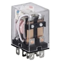
The most popular relay for automation work is the 8 Pin Relay. 8 pin relay has DC or AC coil as the main part. which is connected to two pins. There are two common parts. Underneath a Common part are an NO and an NC part. No part is normally open with a common part and the NC part is normally closed. The timer base used for automation is the same as the 8-relay base. That is, switching can be done using the timer base. This is basically how a relay switch works.
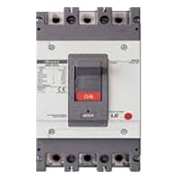
02. TP MCCB:
The MCCB consists of a bimetallic sheet that expands and contracts when the temperature of the MCCB changes. Due to overload, the bimetallic strip will start to bend and eventually, it will trip if more current flows in the circuit than the predetermined current. The trip mechanism opens the breaker. MCCB stands for Molded Case Circuit Breaker. It is another type of electrical protection device that is used when the load current exceeds the limit of a miniature circuit breaker. The MCCB provides Protection against Overload, and Short Circuit Faults and is also used for Switching the Circuits.
03. Capacitor:
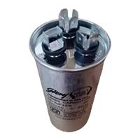
This 50 MFD Capacitor Electric motor Capacitor article Series Explains the Selection, Testing, installation, & use of Electric motor Starter Start and run Capacitors used on Various Electric Motors Found in or at Buildings such as air Conditioner Compressors, fan Motors, and some Good Pumps. An Electric motor’s run Capacitor (50 MFD Capacitor) Remains active after the Starting cap has Dropped from the circuit (as the motor has its proper speed), and 50 MFD Capacitor indeed value of the run Capacitor can affect Motor Speed.
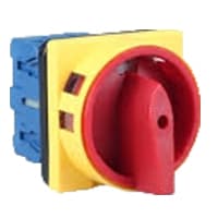
04. Selector Switch:
A Mechanical Switch That can be rotated Left, right, or center to open or close the electrical contacts is known as a Selector switch. The Main Function of This Selector Switch is to Control Devices and also to Switch Between a Minimum of 2 or Above Electrical Circuits. The Perfect Used for Selector Switch is When Used for Controlling an Output of a Device. We know that a Selector switch is Used to control the electrical current flow in a Circuit it can also be used to both Initiate and inhibit the Current Flow.
05. Fuse:
In a 3-phase System Typically only two Fuses will open on a line-to-line short circuit. Since all 3 line currents are offset from each other each fuse will see the full fault at different times. A fuse is a short length of very thin and low melting point conductive wire that can carry a specified amount of current indefinitely when connected to an electrical circuit. If the current flows in excess of the specified amount, the fuse itself melts and isolates the faulty part of the circuit from the source.
Thank You for visiting the website. Keep visiting for more Updates.
Read more Single Phase Wiring
What is a kilowatt-hour (kWh) | kwh formula | What does kwh mean
Introduction to Electrical Units and CircuitskW and kWh on your electricity bill As your home uses electricity during...
What is the Difference Between kVA | What does KVA mean | kVA formula
Difference Between KVA ExplainedWhat does KVA Mean? There are technical terms aplenty when it comes to generators, and...
Power Factor | Power Unit | Energy | Electricity Unit
Power factor definition | Calculating Power FactorPower Factor Values In a purely resistive circuit, the power factor...
0 Comments