Manual light sensor wiring:
This diagram shows a Manual light sensor wiring connection for street lights. In this circuit, we use a three-phase energy meter, a TP MCB ( Tripple Pole Minature Circuit Breaker ), an SP MCB ( Single Pole Miniature Circuit Breaker ), a rotary switch, a light sensor, and a magnetic contactor. This circuit diagram is very simple and easy to make connect it. If you want to know more about this circuit, please check our youtube video below the post. For more information please check our category.
Advertisements
Diagram of Manual light sensor wiring:

Components needed For this Project:
You can get the components from any of the sites below:
- Three Phase Energy Meter [See Buy Click Amazon]
- TP MCB 32A [See Buy Click Amazon]
- SP MCB 10A [See Buy Click Amazon]
- Changeover Switch [See Buy Click Amazon]
- Magnetic Contactor 40A [See Buy Click Amazon]
- Motion Sensor [See Buy Click Amazon]
*Please note: These are affiliate links. I may make a commission if you buy the components through these links. I would appreciate your support in this way!
Advertisements
Components used to make the Manual light sensor wiring:
01. 3 Phase Energy Meter:
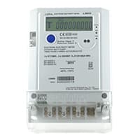
The Meter Which is used for Measuring the Power of the 3-phase supply is known as the 3-phase energy meter. A 3-phase Energy meter is a 3-phase 4-wire direct Connected meter that is Used to estimate the electricity on the Three-phase power supply, mostly for residential & commercial use. A 3-phase meter helps consumers & utilities in revenue protection. The 3-phase meter is Constructed by Connecting the 2 single-phase meters through the shaft.
02. TP MCB:
The full meaning of MCB is Miniature Circuit Breaker for TP MCB. MCB is an electromagnetic switch or device. If for any reason a short circuit occurs in the supply line or load line (line to line or line to neutral) or in case of overload MCB. the MCB automatically trips and disconnects the main line circuit or household power supply Connection. TP MCB In 3 Pole MCB, Switching & Protection is affected in only 3-Phases and the Neutral is not part of the MCB. 3 pole MCB signifies the Connection of Three Wires for a 3-Phase system Red-Yellow-Blue Phase. 3-Phase Supply Only Without Neutral.

03. SP MCB:

In single-pole MCB, Switching and protection are Affected in only one Phase. Single phase supply to break the phase only. A single Pole breaker is Typically used with 120-volt Circuits, and a 6-20 amps Miniature Circuit Breaker. They are constructed with one Line Wire and one Neutral wire. A Single Pole switch is the most basic General-Purpose switch that you use to Control a light or another device from one location. These Switches have 2 Brass-Colored screw Terminals Connected to the hot Power source wires. Pole refers to the number of Circuits Controlled by the Switch SP Switches Control only one Switch Electrical Circuit.
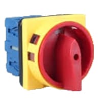
04. Rotary Switch:
A Mechanical Switch That can be rotated Left, right, or center to open or close the Electrical contacts is known as a Selector switch. The Main Function of This Selector Switch is to Control Devices and also to Switch Between a Minimum of 2 or Above Electrical Circuits. The Perfect Used for Selector Switch is When Used for Controlling the Output of a Device. We know that a Selector switch is Used to control the electrical current flow in a Circuit it can also be used to both Initiate and inhibit the Current Flow.
05. Magnetic Contactor:

A magnetic contactor is an electromagnetic switching device. It is generally used for controlling 3-phase Motors. The operation of a magnetic contactor is similar to that of a Relay. but a relay is used for low-power or low-voltage connections, and a magnetic contactor is used for high-power or high-voltage connections. As soon as the supply is applied to the magnetic contactor coil. its normally open contacts are closed and normally closed contacts are opened and the associated devices are also operated. This is how a magnetic contactor works.
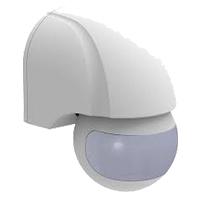
06. Light Sensor:
Photocells and Motion Sensors are Electronic Devices you can use to Manage Indoor or Outdoor Lighting. The Main Difference Between Photocells and Motion Sensors is that the Former Detects change in light Levels, and The Latter React to Physical Movement. Movement in the Detection area Changes the Reflected Signals and Activates the Sensor. They also save Energy by Turning Themselves off when Light is Unnecessary. Many Motion Sensors use a Combination of Detection Methods to Provide enhanced Coverage and eliminate false positives. The adjustable timers built into some Sensors let you Control how long the Attached Lights Remain Active after it Detects Motion.
Thank You for visiting the website. Keep visiting for more Updates.
Frequently asked questions
A 3-phase board, also known as a 3 Phase Distribution Board or TPN is an essential part of a 3-phase electrical installation. It acts as a central hub that receives power supply from the electricity grid or a generator and then distributes it to various circuit diagrams within a building or facility.
In a 3-phase power supply, the voltage on each wire is 120 degrees phase shifted relative to each of the other wires. Because it is an AC system, it allows the voltages to be easily stepped up using transformers to high voltage for the transmission and back down for distribution or giving high efficiency.
A distribution board or distribution panel (DP) is an important part of an electricity power supply system. Its job is to split an incoming electrical power supply feed into multiple secondary or subsidiary circuit diagrams. Most of the time, each of these secondary circuit diagrams will be protected with a fuse or breaker.
3-phase installations are those formed by three different alternating currents diagram that divide the installation into several parts which are reached by a constant power supply. Their standardized powers are currently flow-adapted to 400 volts. Three phases have four wires: three actives (called phases) and one neutral.
Miniature Circuit Diagram Breakers (MCB): A miniature circuit breaker controls the power supply to various miniature circuit diagrams on the main circuit. They switch off if they detect an overcurrent flow i.e. current that supersedes the circuit's diagram current flow rating.
Read more Single Phase Wiring
What is a kilowatt-hour (kWh) | kwh formula | What does kwh mean
Introduction to Electrical Units and CircuitskW and kWh on your electricity bill As your home uses electricity during...
What is the Difference Between kVA | What does KVA mean | kVA formula
Difference Between KVA ExplainedWhat does KVA Mean? There are technical terms aplenty when it comes to generators, and...
Power Factor | Power Unit | Energy | Electricity Unit
Power factor definition | Calculating Power FactorPower Factor Values In a purely resistive circuit, the power factor...
0 Comments