Air Compressor Wiring Circuit Diagram
Learn complete air compressor wiring with motor starter, pressure switch, overload relay, and automatic on-off control for safe and efficient operation.

industrial air compressor wiring
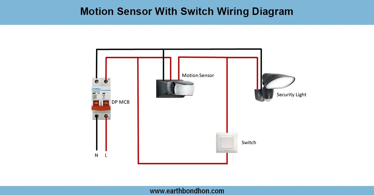
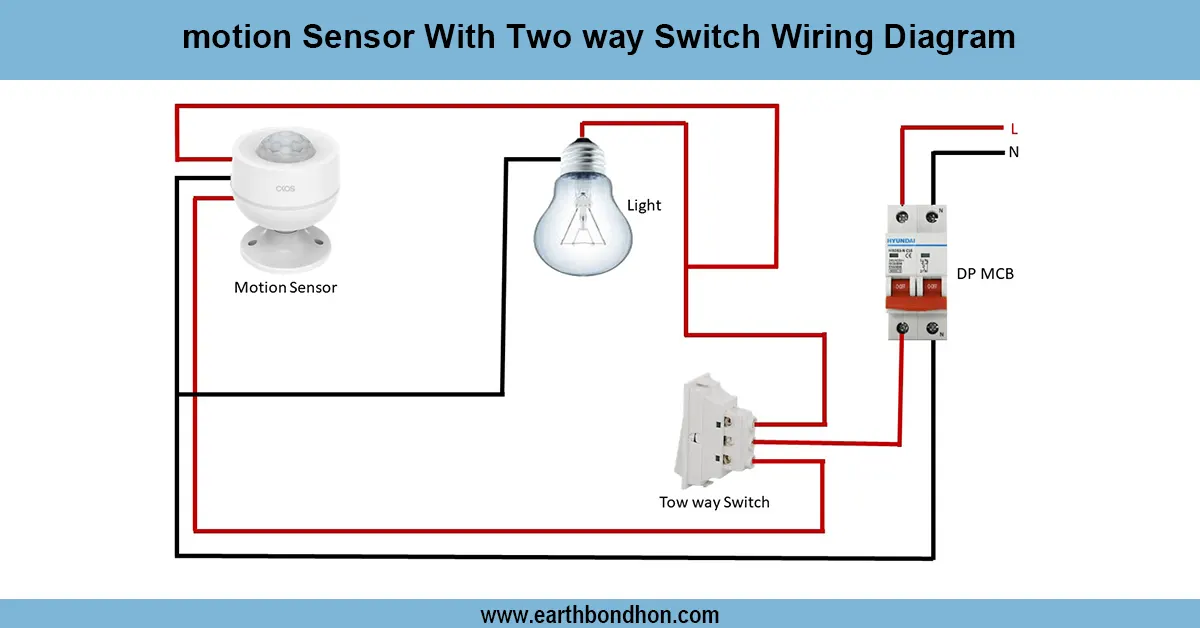
An air compressor Wiring is a diagram illustrating how one goes about connecting the motor, pressure switch, overload relay, and the starter to enable it to automatically switch on and off. The correct wiring is safe, economical, and ensures effective power consumption and reliability of the compressor.
pressure switch compressor connection
The diagram of an air compressor wiring shows how the air compressor works to ensure safe and automated operation with the connection of the motor, pressure switch, starter, and protective devices. The wiring has been set so that the compressor motor is switched on when the tank pressure drops below a predetermined minimum pressure and is switched off when the maximum pressure is achieved. Major elements are motor starter or contactor, overload relay, pressure switch, MCB or fuse, and correct earthing and neutral connections. This arrangement eliminates overcurrent, safeguards the motor, and makes the operation of the setup power efficient. This wiring is used in industrial and workshop compressors to be controlled automatically, eliminating the manual operation and avoiding the destruction of equipment. Correct connection also applies to the proper operation of the motor with the correct phase sequence and voltage. Evaluating/adjusting Testing and diagnostic procedures involve checking the pressure switch settings, insulation resistance, proper rotation of the motor, and protective equipment.
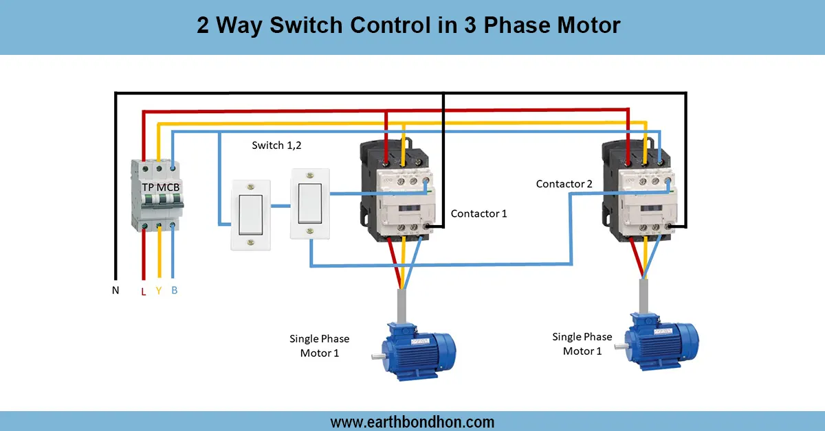
Work & Installation (Input → Output Summary)
- Power Supply enters the compressor control panel.
- Motor Starter Contactor connects power to the compressor motor.
- Pressure Switchcontrols motor start/stop based on tank pressure.
- Overload Relay protects the motor from overcurrent.
- MCB/Fuse provides additional circuit protection.
- Neutral & Earth connections ensure safety.
- Compressor motor starts and stops automatically according to pressure demand.
Testing & Final Adjustments
- Verify insulation resistance of the motor and wiring.
- Check the phase sequence and voltage at motor terminals.
- Set the minimum and maximum pressure levels on the pressure switch.
- Energize the system and observe motor starting at low pressure.
- Confirm automatic motor stop at maximum pressure.
- Test overload relay by simulating overcurrent; ensure it trips correctly.
- Inspect all connections for proper tightening and earthing.
- Ensure MCB/fuse provides correct protection.
- Verify smooth operation without sparking or vibration.
- Record test results to confirm reliable automatic operation before regular use.
Frequently Asked Questions - Air Compressor Wiring Circuit Diagram:
What is an air compressor wiring diagram?
A schematic showing how to wire the motor, pressure switch, starter, and protective devices.
Why use automatic on-off wiring?
To start and stop the compressor motor automatically based on tank pressure.
Which devices are required?
Motor starter/contactor, pressure switch, overload relay, MCB/fuse, and earthing.
How does the pressure switch work?
It closes the circuit at low pressure to start the motor and opens at high pressure to stop it.
Is overload protection necessary?
Yes, to prevent motor damage from overcurrent.
Can this wiring be used for single-phase compressors?
Yes, with correct motor starter and pressure switch selection.
How to test the wiring?
Check insulation, motor rotation, pressure switch operation, and protective device function.
Is earthing required?
Yes, for safety against electric shock and equipment protection.
How to adjust pressure levels?
Set the minimum and maximum levels on the pressure switch according to requirement.
Where is this wiring commonly used?
Industrial, workshop, and residential air compressors for automatic operation.