Air Compressor wiring diagram:
This diagram shows how to make an Air Compressor wiring diagram. In this circuit, we use a TP MCB ( Tripple Pole Minature Circuit Breaker ), an SP MCB ( Single Pole Miniature Circuit Breaker ), a magnetic contactor, an overload, a DPST Switch, and a three-phase energy meter. This circuit is very simple and easy to make. If you want to know more about this circuit please stay check our youtube video for clear details.
Advertisements
Diagram of Air Compressor wiring:

Components needed For this Project:
You can get the components from any of the sites below:
- Air Compressor Max 150 PSI Pressure[See Buy Click Amazon]
- TP MCB 32A [See Buy Click Amazon]
- Magnetic Contactor 40A [See Buy Click Amazon]
- Motor Protector Overload [See Buy Click Amazon]
- SP MCB 10A [See Buy Click Amazon]
- DP 20A Switch [See Buy Click Amazon]
*Please note: These are affiliate links. I may make a commission if you buy the components through these links. I would appreciate your support in this way!
Advertisements
Components used to make the Air Compressor wiring diagram:
01. Air Compressor:
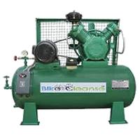
Air is Compressed by air Compressors. Air Compressors draw in Air at an Inlet Valve, They Then Compress The Air to The Required Volume And Release The Pressurized air through the discharge Valve into a Storage Tank. Air Compressors Work by Forcing Atmospheric air Under Pressure to Create Potential Energy That Can be Stored in a Tank for Later used. Just like an Open Balloon. The Pressure Builds up When the Compressed Air is Deliberately Released. Converting The Potential Energy into Usable Kinetic Energy is used.
02. TP MCB:
The full meaning of MCB is Miniature Circuit Breaker for TP MCB. MCB is an electromagnetic switch or device. If for any reason a short circuit occurs in the supply line or load line (line to line or line to neutral) or in case of overload MCB. the MCB automatically trips and disconnects the main line circuit or household power supply Connection. TP MCB In 3 Pole MCB, Switching & Protection is affected in only 3-Phases and the Neutral is not part of the MCB. 3 pole MCB signifies the Connection of Three Wires for a 3-Phase system Red-Yellow-Blue Phase. 3-Phase Supply Only Without Neutral.

03. Magnetic Contactor:

A magnetic contactor is an electromagnetic switching device. It is generally used for controlling 3-phase Motors. The operation of a magnetic contactor is similar to that of a Relay. but a relay is used for low-power or low-voltage connections, and a magnetic contactor is used for high-power or high-voltage connections. As soon as the supply is applied to the magnetic contactor coil. its normally open contacts are closed and normally closed contacts are opened and the associated devices are also operated. This is how a magnetic contactor works.
04. Overload Relay:
Overload Protection is Protection Against a Running Overcurrent That Would Cause Overheating of The Protected Equipment. Hence, An Overload is Also a Type of Overcurrent flow. Overload Protection Typically Operates on an Inverse Time curve where the Tripping Time Becomes less as the Current Increases. This Overload Protector is an Essential Component for Many Sockets Power Systems. The Top-Quality Overload Protector can Effectively Protect Electrical Products from Power Surges.

05. SP MCB:

In single-pole MCB, Switching and protection are Affected in only one Phase. Single phase supply to break the phase only. A single Pole breaker is Typically used with 120-volt Circuits, and a 6-20 amps Miniature Circuit Breaker. They are constructed with one Line Wire and one Neutral wire. A Single Pole switch is the most basic General-Purpose switch that you use to Control a light or another device from one location. These Switches have 2 Brass-Colored screw Terminals Connected to the hot Power source wires. Pole refers to the number of Circuits Controlled by the Switch SP Switches Control only one Switch Electrical Circuit.
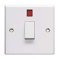
06. 20A DP Switch:
20 amp Double Pole Switches are generally used with Electrical appliances that need to be hard-wired as opposed to using a Plug and power Socket. Double pole switches make it possible to isolate appliances safely from the power supply source. double pole switches or DP switches are exclusively designed to control 2 different electrical circuits at the same time.
Thank You for visiting the website. Keep visiting for more Updates.
Frequently asked questions
The suction valve connects the compressor to the low-pressure side of the system via the suction line that carries refrigerant into the compressor. The discharge valve connects the compressor to the high-pressure side of the system via the discharge line which carries refrigerant after it has been compressed.
To determine the air compressor's amp draw, look at variables like its size. Pancake types may require 7.5 to 10 amps while 12-volt portable air compressors may have amperage specifications of 10 to 30 amps.
For a 240-volt single-phase unit, the breaker size would be likely a 40 amp. Review the nameplate data, appears that you know would have an approximate amp draw of 21.0 AMPS. You may want to install a starter relay for it which would have overloads designed specifically for that motor.
You could look at the amps to see the correct horsepower on it. A 5 hp will be around 21 amps, and a 7.5 hp will be around 35 amps.
kW stands for kilowatts, which is a measure of power supply. In industrial air compressors, kW refers to the amount of power supply required to run the compressor motor. This is a critical factor in determining the efficiency of an air compressor as it affects the amount of energy consumed and the cost of operating the compressor.
Read more Single Phase Wiring
What is a kilowatt-hour (kWh) | kwh formula | What does kwh mean
Introduction to Electrical Units and CircuitskW and kWh on your electricity bill As your home uses electricity during...
What is the Difference Between kVA | What does KVA mean | kVA formula
Difference Between KVA ExplainedWhat does KVA Mean? There are technical terms aplenty when it comes to generators, and...
Power Factor | Power Unit | Energy | Electricity Unit
Power factor definition | Calculating Power FactorPower Factor Values In a purely resistive circuit, the power factor...
0 Comments