Automatic star delta control circuit:
This diagram shows how to make an automatic star delta control circuit. In this circuit, we use a DP MCB ( Double Pole Miniature Circuit Breaker ), 3 magnetic contactors, an overload, an 8-pin relay, push button ( start and stop ). First, we input power to DP MCB, then input power line from DP MCB to Magnetic contactors like this diagram. If you want to connect this circuit like our diagram, please check our youtube video below the link.
Advertisements
Diagram of Automatic star delta control circuit:

Components needed For this Project:
You can get the components from any of the sites below:
- DP MCB 20A [See Buy Click Amazon]
- Magnetic Contactor 40A [See Buy Click Amazon]
- 8 Pin Relay (220V AC) [See Buy Click Amazon]
- Push Button NO Switch [See Buy Click Amazon]
- Push Button NC Switch [See Buy Click Amazon]
- Indicator Light 220v AC [See Buy Click Amazon]
*Please note: These are affiliate links. I may make a commission if you buy the components through these links. I would appreciate your support in this way!
Advertisements
Components used to make the Automatic star delta control circuit:
01. DP MCB:

DP MCB In 2 Pole MCB, switching & protection is affected in phases and the neutral. A Double Pole or DP Switch is a Switch that Controls 2 Circuits at the same time. In terms of Residential Switching, this Normally means it Switches the live and Neutral at the same time. In Layperson Terms, Double Pole switches or DP Switches are Exclusively Designed to Control 2 Different Electrical Circuits at the same time, which allows the Appliances to Isolate safely and reliably. Fan or light Combinations and Medical Equipment are some of the many applications for DP Electrical Switches and Electrical components.
02. Magnetic Contactor:
A magnetic contactor is an electromagnetic switching device. It is generally used for controlling 3-phase Motors. The operation of a magnetic contactor is similar to that of a Relay. but a relay is used for low-power or low-voltage connections, and a magnetic contactor is used for high-power or high-voltage connections. As soon as the supply is applied to the magnetic contactor coil. its normally open contacts are closed and normally closed contacts are opened and the associated devices are also operated. This is how a magnetic contactor works.

03. 8-Pin Relay:
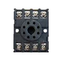
A timer is a type of time-switching device that controls and controls Electrical circuits and electrical and electronic devices through time setting (on/off). The timer is basically 8-pin. Like other controlling devices the timer has a coil and when this coil is magnetized, the timer works on/off. The timer has 2 common ends and each common end has normally close and normally open options. When the timer is set by time, the timer trips at the end of that time and turns the common is normally closed (on) to open (off) and normally open (off) to close (on). This is how the timer works.
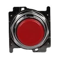
04. Start Button:
NO (Normally Open) Terms Refer to a Type of Dry Contact or Wet Contact. A Push to Make Switch Allows Electricity to flow Between its 2 contacts when held in. When the button is released, the Circuit is broken. This type of Switch is also known as A Normally Open (NO) Switching system. As its name implies, a Normally Open (NO) Switch Contact or “a Contact” is a Switch. Put very simply, a Normally Open Sensor will have no Current When in a Normal State But When it Enters an Alarm State it will have +5V applied to the Circuit.

05. Stop Button:
An NC (Normally Closed) Push Button is a Push Button That, In Its Default State, Makes Electrical Contact With The Circuit. An NC (Normally Closed) Push Button is a Push Button that, in its Default State, Makes electrical Contact With the Circuit. When The Button Is Pressed Down, The Switch no Longer Makes Electrical Contact And The Circuit is Now Open. When The Button is Not Pressed, Electricity Can Flow, But When it is Pressed The Circuit is Broken. This type Of Switch is Also known As a Normally Closed (NC) Switch.
06. Indicator Light:
An indicator lamp just Sounds Technical, Sometimes it is called a Supervisory light Indicator. Indicator lights are amber in color and can be located at the Front, the Rear, and Sometimes at the Side of the car on both the left And Right-hand sides. The Common colors used by Indicator lamps are red, yellow, blue, white, and green line system. A Panel Indicator Lamp Generally has up to 5 Differently Colored Segments to Indicate Various Conditions on the Machine or Process system.

Thank You for visiting the website. Keep visiting for more Updates.
Frequently asked questions
A star delta of the starter is the most commonly used method for the starting of a three-phase induction motor. In star delta starting an induction of the motor is connected in through a star connection throughout the starting period. Then once the motor reaches the required of the speed motor is connected through a delta connection.
Star delta starters are another device that may be used to reduce current flow demand during motor startup. It is often used for starting 3-phase induction motors, but could only be used when starting the motor without load and when the required starting current flow is relatively low.
The main reason for using a timer in a star-delta starter is to allow the motor to start in a low-voltage, low-current star configuration and then switch to a high-voltage, high-current delta configuration after a specific time interval.
This sequential switching helps reduce the starting current and provides a smoother transition for the motor, thereby preventing electrical and mechanical stress. Two timers one is an ON delay timer and another is an OFF delay timer. ON delay timer is used for making on the Star and Delta contactor.
A Star Connection is a four–wire connection (4th wire is optional in some cases) A Delta Connection is a four–wire connection. Two types of Star Connection systems are possible: 4–wire, 3 – phase system, and 3 – wire 3 phase system. In Delta Connection, only a 3 – 3-wire 3-phase system is possible.
Read more Single Phase Wiring
What is a kilowatt-hour (kWh) | kwh formula | What does kwh mean
Introduction to Electrical Units and CircuitskW and kWh on your electricity bill As your home uses electricity during...
What is the Difference Between kVA | What does KVA mean | kVA formula
Difference Between KVA ExplainedWhat does KVA Mean? There are technical terms aplenty when it comes to generators, and...
Power Factor | Power Unit | Energy | Electricity Unit
Power factor definition | Calculating Power FactorPower Factor Values In a purely resistive circuit, the power factor...
0 Comments