Automatic Timer Relay Using Alarm:
This diagram shows how to make Automatic Timer relay Using an Alarm. In this circuit, we use an alarm siren, a timer, an SP MCB ( Single Pole Miniature Circuit Breaker ), and a relay. First, we need to input the phase line into the MCB, then input the connection to the timer, relay, and alarm siren as in our diagram. Then we need to input a neutral connection to all components. Now this circuit is ready for use. If you want to know more details about this circuit please check our youtube video below the post.
Advertisements
Diagram of Automatic Timer relay Using Alarm:

Components needed For this Project:
You can get the components from any of the sites below:
- SP MCB 10A [See Buy Click Amazon]
- 8 Pin Timer 220V AC [See Buy Click Amazon]
- 8 Pin Relay (220V AC) [See Buy Click Amazon]
- Alarm Siren [See Buy Click Amazon]
- Terminal Block [See Buy Click Amazon]
*Please note: These are affiliate links. I may make a commission if you buy the components through these links. I would appreciate your support in this way!
Advertisements
Components used to make the Automatic Timer relay Using Alarm:
01. SP MCB:

In single-pole MCB, Switching and protection are Affected in only one Phase. Single phase supply to break the phase only. A single Pole breaker is Typically used with 120-volt Circuits, and a 6-20 amps Miniature Circuit Breaker. They are constructed with one Line Wire and one Neutral wire. A Single Pole switch is the most basic General-Purpose switch that you use to Control a light or another device from one location. These Switches have 2 Brass-Colored screw Terminals Connected to the hot Power source wires. Pole refers to the number of Circuits Controlled by the Switch SP Switches Control only one Switch Electrical Circuit.
02. Timer:
A timer is a type of time-switching device that controls and controls Electrical circuits and electrical and electronic devices through time setting (on/off). The timer is basically 8-pin. Like other controlling devices the timer has a coil and when this coil is magnetized, the timer works on/off. The timer has 2 common ends and each common end has normally close and normally open options. When the timer is set by time, the timer trips at the end of that time and turns the common is normally closed (on) to open (off) and normally open (off) to close (on). This is how the timer works.

03. 8-Pin Relay:
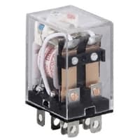
The most popular relay for automation work is the 8 Pin Relay. The 8-pin relay has a DC or AC coil as the main part. which is connected to two pins. There are two common parts. Underneath a Common part are a NO and an NC part. No part is normally open with a common part and the NC part is normally closed. The timer base used for automation is the same as the 8-relay base. That is, switching can be done using the timer base. This is basically how a relay switch works for the relay.
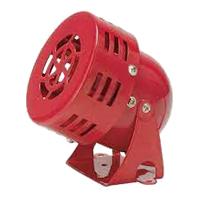
04. Alarm Siren:
A Siren is a loud noise-making device. Civil Defense Sirens are Mounted in Fixed Locations and Used to Warn of Natural Disasters or Attacks. Sirens are Wsed on Emergency service Vehicles Such as ambulances, Police Cars, And fire Engines. There are 2 General types: Mechanical and Electronic. A civil Defense siren, also known as an air-raid siren or Tornado Siren. is a Siren Used to Provide an Emergency Population Warning to the General Population of Approaching Danger system.
05. Terminal Block:
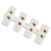
A Siren is a loud noise-making device. Civil Defense Sirens are Mounted in Fixed Locations and Used to Warn of Natural Disasters or Attacks. Sirens are Wsed on Emergency service Vehicles Such as ambulances, Police Cars, And fire Engines. There are 2 General types: Mechanical and Electronic. A civil Defense siren, also known as an air-raid siren or Tornado Siren. is a Siren Used to Provide an Emergency Population Warning to the General Population of Approaching Danger system.
Thank You for visiting the website. Keep visiting for more Updates.
Frequently asked questions
A control relay allows an electrical current to flow through a conducting coil that opens and closes a switch. It also protects the circuit current. With a control relay, users do not need to manually turn the switch to isolate and change the state of an electric circuit diagram.
Scheduling when your Windows 10 PC shuts down makes everything more convenient or secure. Simply set a shutdown timer or once your PC has been inactive for a certain period of time, the system will shut down. This protects your PC from unwanted access or unnecessary energy waste.
With timer operation, the Time Switch controls the output according to the set ON or OFF times. With pulse-output operation, the Time of the Switch outputs a pulse of a specified time width at the set ON time. The power supply is turned ON by a Time Switch.
On a conventional Control Relay, the contacts are opened and closed when a voltage is applied and removed from the coil, however, for timer relays the contacts would open or close before and after an intentional time period.
You are correct that a relay is basically just a switch, but it is a switch operated via remote control, so to speak. A regular switch controls electrical current flow by connecting or breaking the path of either the positive side of a circuit (most common) or the negative side of a circuit diagram.
Read more Single Phase Wiring
What is a kilowatt-hour (kWh) | kwh formula | What does kwh mean
Introduction to Electrical Units and CircuitskW and kWh on your electricity bill As your home uses electricity during...
What is the Difference Between kVA | What does KVA mean | kVA formula
Difference Between KVA ExplainedWhat does KVA Mean? There are technical terms aplenty when it comes to generators, and...
Power Factor | Power Unit | Energy | Electricity Unit
Power factor definition | Calculating Power FactorPower Factor Values In a purely resistive circuit, the power factor...
0 Comments
Trackbacks/Pingbacks